


16
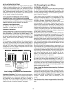
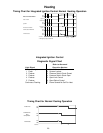
Sizing Between Single or Second Stage Regulator and Appliance*
Maximum Propane Capacities Listed are Based on 1/2" W.C. pressure drop at 11" W.C. setting.
Capacities in 1,000 BTU/hour.
Pipe or
Nominal Pipe Size
Tubing Tubing Size, O.D. Type L
Schedule 40
Length, 3/8" 1/2" 5/8" 3/4" 7/8" 1-1/8" 1/2" 3/4" 1" 1-1/4" 1-1/2"
Feet
10 39 92 199 329 501 935 275 567 1,071 2,205 3,307
20 26 62 131 216 346 630 189 393 732 1,496 2,299
30 21 50 107 181 277 500 152 315 590 1,212 1,858
40 19 41 90 145 233 427 129 267 504 1,039 1,559
50 18 37 79 131 198 376 114 237 448 913 1,417
60 16 35 72 121 187 340 103 217 409 834 1,275
80 13 29 62 104 155 289 89 185 346 724 1,066
100 11 26 55 90 138 255 78 162 307 630 976
125 10 24 48 81 122 224 69 146 275 567 866
150 9 21 43 72 109 202 63 132 252 511 787
200 8 19 39 66 100 187 54 112 209 439 665
250 8 17 36 60 93 172 48 100 185 390 590
*Data in accordance with NFPA pamphlet NO. 54
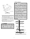
WARNING
To prevent death, serious personal injury
or property damage due to fire or explosion
caused by a propane gas leak, install a gas
detecting warning device.
WARNING
If the propane gas furnace is installed in a
basement, an excavated area or a confined
space, a warning device is required due to:
• Propane gas is heavier than air and any
leaking gas can settle in any low areas
or confined spaces.
• Propane gas odorant may fade, making
the gas undetectable except with a
warning device.
If the presence of gas is suspected, follow
the instructions on Page 2 of this manual.
VIl. Electrical Wiring
WARNING
To prevent death or personal injury due to
electric shock, disconnect electrical power
before changing any electrical wiring.
CAUTION
When servicing controls, label all wires
before disconnecting. Wiring errors can
cause improper and dangerous operation.
After servicing is completed, always verify
proper operation.
The unit wiring harness is an integral part of the furnace.
Field alteration to comply with electrical codes should not
be required.
Power supply to the furnace must be NEC Class 1, and
must comply with all applicable codes. The furnace must be
electrically grounded in accordance with the local codes or,
in their absence, with the latest edition of the National
Electrical Code, ANSI NFPA No. 70 and/or the CSA C22. 1
Electrical Code. A fused disconnect must be provided and
sized in accordance with the unit maximum overcurrent
protection.
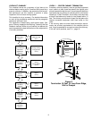
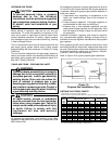
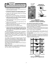
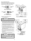
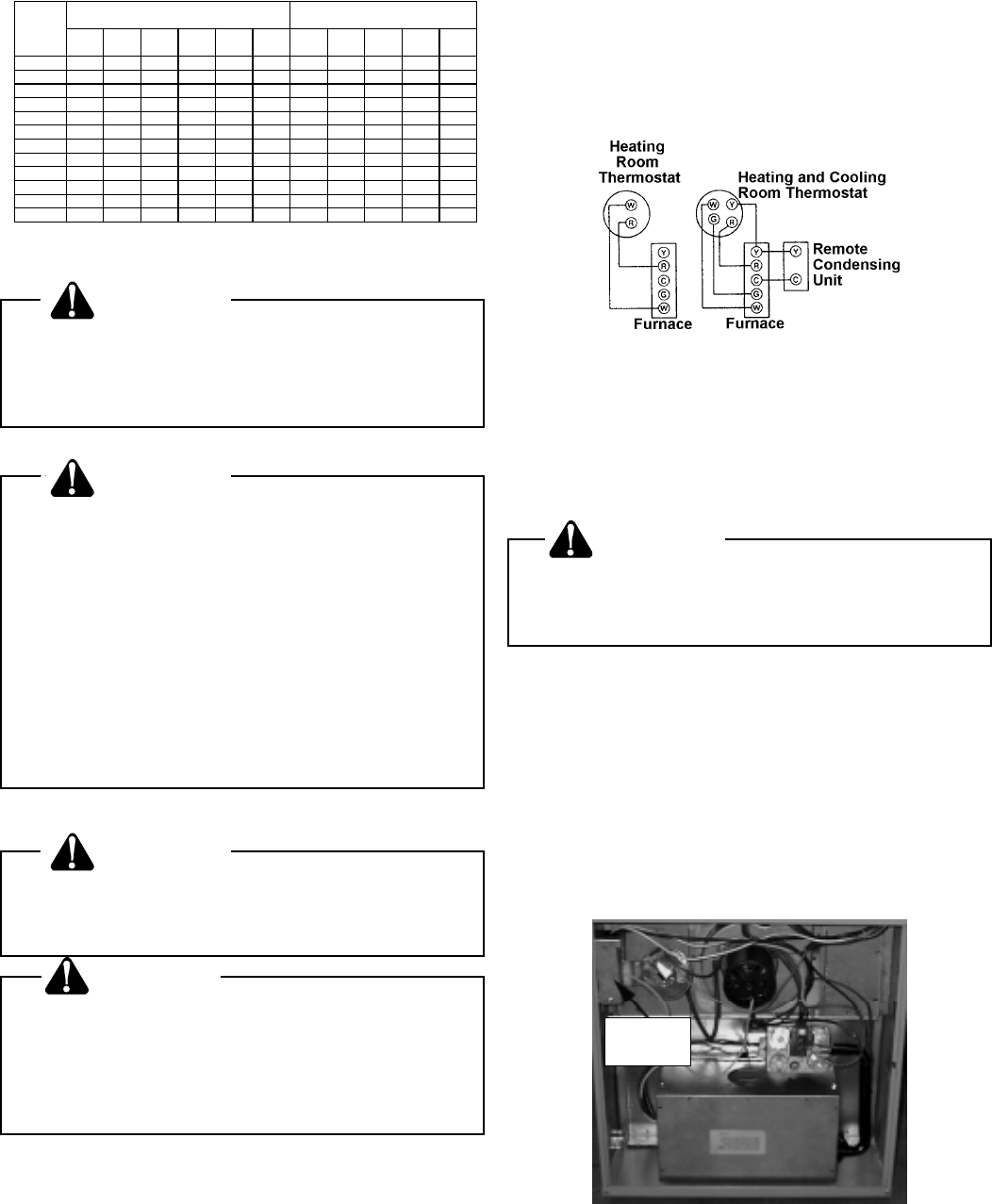
Figure 20
Typical Field Wiring
(24 VAC Control Circuit)
A 40 VA transformer and an integrated electronic control
are built into the furnace to allow use with most cooling
equipment.
CAUTION
To avoid the risk of electrical shock, wiring
to the unit must be properly polarized and
grounded.
To provide more reliable sensing of flame, the
ground wire
must run to the electrical panel.
Line voltage wiring
must enter into the junction box pro-
vided with the furnace.
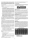
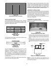
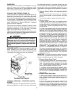
As shipped, the junction box is attached to the left side of
the furnace (as viewed for an upflow installation). If this is
suitable for your installation, no changes are necessary.
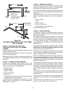
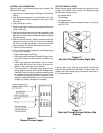
If the line voltage wiring is to enter through the right side of
the furnace (as viewed for an upflow installation), relocate
the junction box as shown in Figure 21.
Figure 21
Junction Box (Left Side)
Junction
Box