14
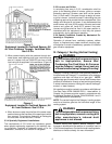
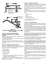
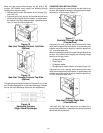
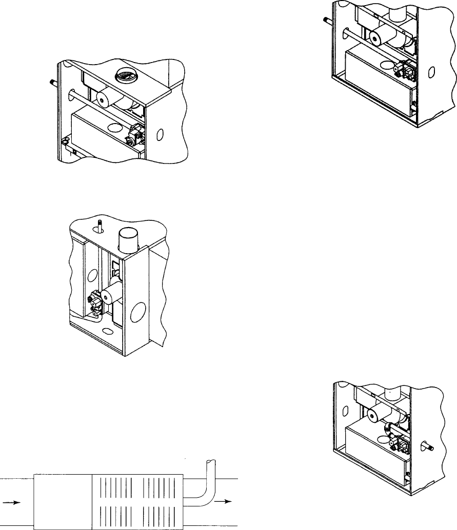
When the gas piping enters through the left side of the
furnace, the installer must supply the following fittings
(starting from the gas valve):
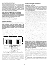
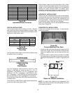
• Straight pipe to reach the exterior of the furnace (Fig-
ures 14 & 15).
• A ground joint union, drip leg, and manual shutoff valve
must also be supplied by the installer. In some cases,
the installer may also need to supply a transition piece
from 1/2 inch to another pipe size.
Figure 14
Gas Inlet Through Furnace Left Side
(Upflow)
Figure 15
Gas Inlet Through Furnace Top Side
(Upflow)
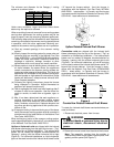
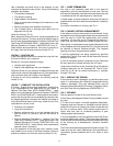
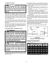
The gas piping connections shown in Figures 13 and 14 are
for a furnace equipped for a right hand discharge. Adapta-
tion for left hand discharge should be self explanatory.
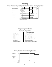
Figure 16
Horizontal Furnace
(Right Hand Discharge)
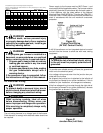
COUNTERFLOW INSTALLATIONS
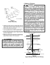
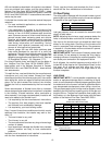
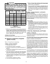
When the gas piping enters through the left side of the
furnace, the installer must supply a straight pipe to reach
the exterior of the furnace (Figure 17).
Figure 17
Gas Inlet Through Left Side
(Counterflow)
A ground joint union, drip leg, and manual shutoff valve
must also be supplied by the installer. In some cases, the
installer may also need to supply a transition piece from
1/2" to another pipe size.
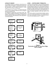
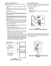
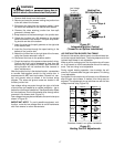
When the gas piping enters through the right side of the
furnace, the installer must supply the following fittings
(starting at the gas valve):
• 90 degree elbow.
• Close nipple.
• 90 degree elbow.
• Straight pipe to reach exterior of furnace (Figure 18).
A ground joint union, drip leg, and manual shutoff valve
must also be supplied by the installer. In some cases, the
installer may also need to supply a transition piece from
1/2 inch to another pipe size.
Figure 18
Gas Inlet Through Right Side
(Counterflow)
“Left side” and “right side” above are as viewed for a
counterflow installation. Adaptation for horizontal airflow
should be self explanatory.


