


19
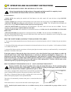
Adjustment #5: Alignment and Initial Test of Safe Finish Photosystem
A. Keep a portable transmitter with you to control the garage door opener. The red light on the receiver unit should now be on. If
not, recheck that the mounting screws are tight then, if necessary, align the photosystem by slightly bending the wall bracket
until proper operation is obtained.
B. Place an object (packing insert box or a similar object approximately six inches high) one foot in front of the transmitter or
receiver. The red LED should go OFF and remain OFF until the object is removed. NOTE: There may be a slight delay in
returning to normal depending upon how long the photosystem was blocked. If the light fails to go off when the object is placed
in the path of the beam check the wire connections and the installation height of the units (see Page 13).
C. Move to the center of the door. Make sure the red LED light is on. Move a solid object slowly through the beam. The
LED should go OFF and then ON.
D. Using the pushbutton or transmitter, activate the opener and check that it will operate through the full open and close cycles. If
not, re-align the photosystem by slightly bending the wall bracket until proper operation is obtained.
E. Tighten all mounting screws and bolts, loop and secure any extra wire.
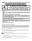
12”
12”
6”
12”
Sensor
Garage Door
Opening
110055-2
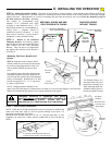
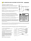
Important Test: Photoelectric Obstruction Test
Test Procedure
Place an object 6” x 12” on the floor (as illustrated)
progressively on foot from the left side of the door; center of
the door and one foot from the right side of the door. The
object must prevent an open door from closing in any other
mode other than constant pressure on the wall button. The
object should also cause a closing door stop and reverse to
the open position. If it doesn’t, the Safe Finish photoelectric
system must be adjusted lower and the test repeated until the
door responds properly to the 6” object.
If adjustments are needed, refer to preceding adjustment.
If the unit still will not respond and fails this obstruction
sensing beam test, the door may cause severe injury or death.
Have a qualified service person make repairs.
E: OPERATION AND ADJUSTMENT INSTRUCTIONS
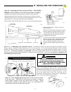
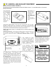
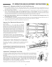
Adjustment #7 :Resetting the Travel Timer
Your opener is shipped with the jumper connected, allowing the operator to run continuously for
17 seconds, then stop in the Open cycle or reverse in the closing cycle, activating the flashing
light mode.
On all doors having over 9 feet of travel, it is necessary to cut the run timer jumper on the motor
control board to allow the opener to run for 29 seconds. Disconnect the power from the opener
before removing cover and cutting the jumper. MAKE SURE YOU DISCONNECT THE
POWER BEFORE CUTTING THE JUMPER. THE RUN TIMER WILL NOT CHANGE IF
THE JUMPER IS CUT WITH THE POWER CONNECTED.
This jumper is located under operator cover on the control board, as illustrated.
110057-2
Cut and
Separate
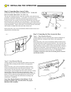
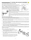
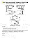
Adjustment #6: Positive Mechanical Lock Adjustment
The garage door opener is designed with an automatic mechanical
locking system. This lock secures the door in the fully closed
position.
To adjust, activate your opener and allow the door to go to its
fully closed position. Loosen the two screws on the rail stop
and move it behind behind the chain latch assembly with a gap
of 1/2” between “stop” and “latch”.
Rail “Stop”
“Latch”
Stop Limits
1/2”
110057-1