


17
E: OPERATION AND ADJUSTMENT INSTRUCTIONS
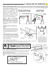
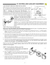
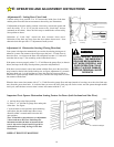
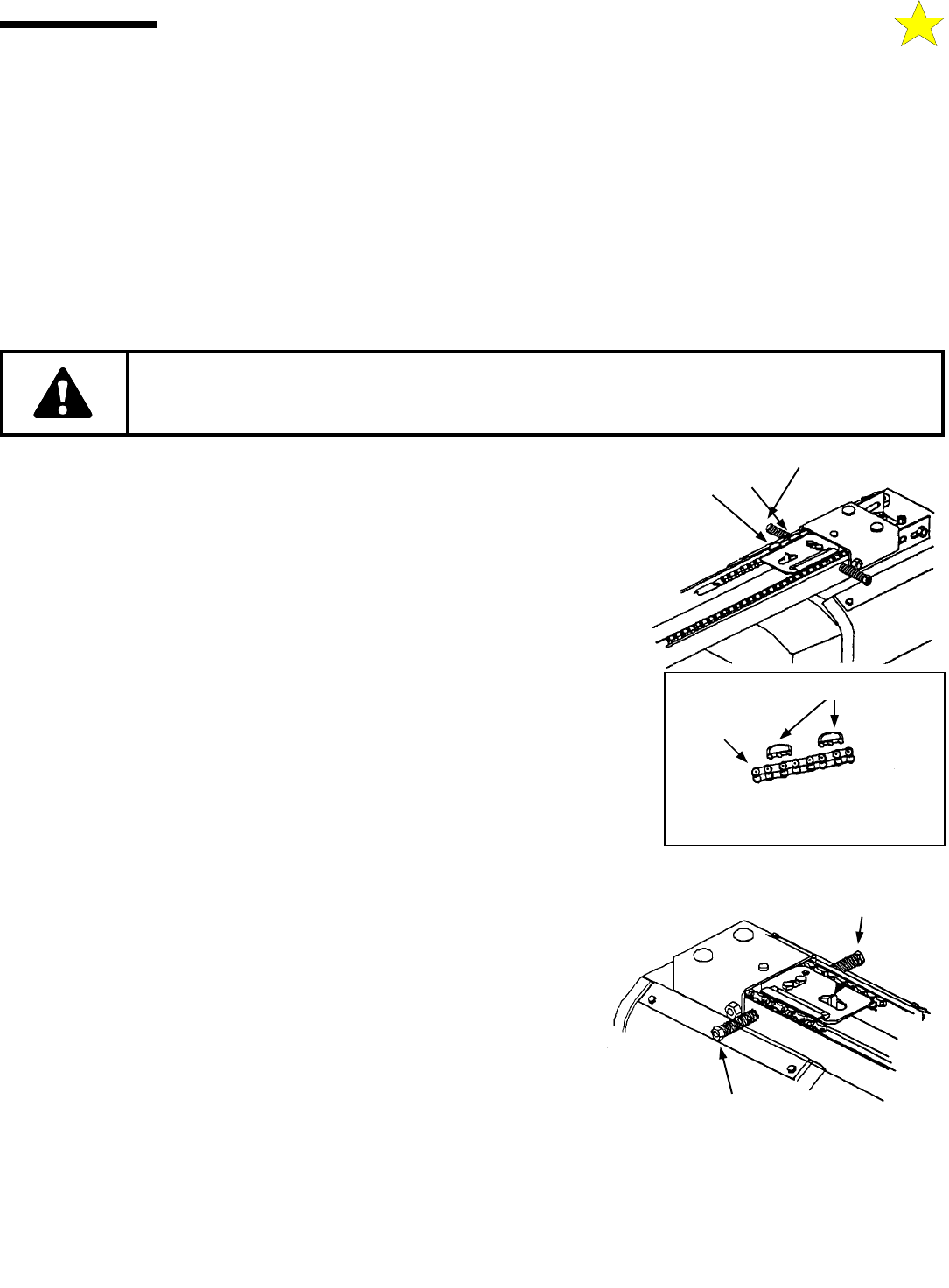
Adjustment #1: Opening Travel
Your opener is assembled at the factory with the trolley in the forward position with the
open limit stops snapped in place on the chain, set for a standard door.
If you door is non-standard, move BOTH open limit stops, located just behind the trolley.
As an example: For a 6 FT, 6 INCH door, move both open limit stops six inches or 12 links
toward the power head unit.
To confirm final opening travel adjustment, activate the opener to bring the foor to the
fully open position. When properly adjusted, center of the open limit stops should come to
rest opposite the load adjusting nut.
NOTE: If the door drifts forward, move the open limit stops toward the
power head unit. If the door does not drift forward it is still advised that you
perform one additional check. Operate manual release on the trolley and
allow the door to seek its natural fully open position, then move the open limit
stops to align trolley to this position. If the door does not open fully at its
natural open position, it indicates a door spring or hardware problem that
should be referred to a door system professional.
(See instruction label on side of track for proper limit stop location.)
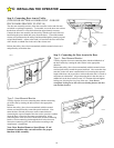
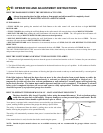
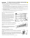
Adjustment #2: Opening and Closing Force
Hex nuts for adjusting force are located on either side of the rail at the motor end.
The left hex nut, labeled “CLOSE”, adjusts the closing force; the right hex nut,
labeled “OPEN”, adjusts the opening force.
Turning the hex nuts clockwise increases force; counterclockwise decreases force.
Your garage door opener is built with a safety system that allows the door to reverse
in the close direction and stop in the open direction. This must be adjusted so your
opener does not use excessive force in the down direction or react to the weight of the
door during upward travel.
To help determine that the force is not excessive, grasp the door handle or bottom
edge during downward travel. The opener should reverse to this force. Do not stand
under the door during this test.
If the handle is hard to hold and the door does not reverse, adjust the CLOSE hex nut to decrease force until the door reacts properly.
Repeat the adjustment procedure for upward travel. The door should stop without using excessive force.
DO NOT USE ADJUSTMENTS TO COMPENSATE FOR A POORLY WORKING DOOR. THIS WILL
INTERFERE WITH THE PROPER OPERATION OF THE REVERSING MECHANISM AND MAY
DAMAGE THE DOOR.
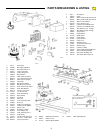
Open Adjustment Nut
Close Adjustment Nut
Leave One Link Open Between
the Two Open Limit Stops
Limit Stops
Chain
Load Adjusting Nut
Limit Stops
110056-2
110056-1
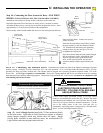
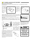
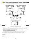
OPTIONAL THREE FUNCTION DELUXE WALL STATION
When the Wall Station is connected to the operator per instructions supplied with the wall station, it will provide the following
features:
1. “OFF-ON” will prevent inadvertent operation of the door from any other push button, radio or keyless entry device. It will also
as additional protection from unwanted operation during absence of the owner. This feature is to be activated only when the door is
at the full open or close position and never while the door is moving.
2. “LIGHT” button allows the convenience light to be turned on and stay on until turned off by a second push of the button or
activation of the door cycle.
3. “UP/DOWN” button provides normal opening and closing of the door by momentary activation of this push button. Function of
door cycle is described above - “How the Door Moves When the Opener is Activated”.