


11
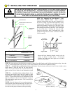
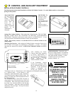
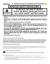
Step 12: Install a Rough Service lamp bulb (75 Watt maximum) firmly
in the light socket. Light bulbs in Door Openers are subject to vibration
during normal operation which may shorten their life spans. Rough
Service bulbs, available at most hardware stores, are recommended. Fit
Light Diffuser tabs into the panel tabs as shown.
Clips
110051-3
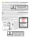
C: INSTALLING THE OPERATOR
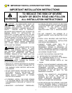
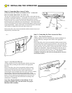
STEP 11: Connecting The Electrical Power Consult the label on the rear panel of the Opener to determine its proper
working voltage. Normally it will be marked for 115V, 60 cycle operation. (If it is an export model designed for 220V, 50 cycle
operation, the label will clearly indicate this.) The Opener must be plugged into a properly grounded receptacle within 3 FT of the
Power Unit. A GFI Type receptacle is recommended. Do not use 2-prong adapters and do not use extension cords for anything
more than temporary hook-up and testing purposes. Receptacle wiring should be No. 14 or heavier, and must be in compliance with
local building and electrical codes.
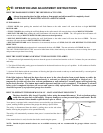
If local codes require permanent wiring, a GFI type circuit
breaker is recommended to protect the line. Remove the Strain
Relief Bushing and withdraw the Line Cord from the rear of the
Power Unit to expose the three insulated connectors. Cut the
wire at the rubber jacket of the Line Cord and wire in
permanently, employing proper wiring practices. Discard Strain
Relief. It is not used with permanent wiring.
Using the two wires (black & white) that were left when you
cut off the line cord, splice in the permanent connections.
Permanent Wiring Connection
Normal
Connection
Ground Wire
110053-1
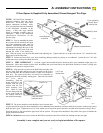
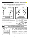
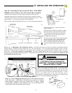
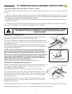
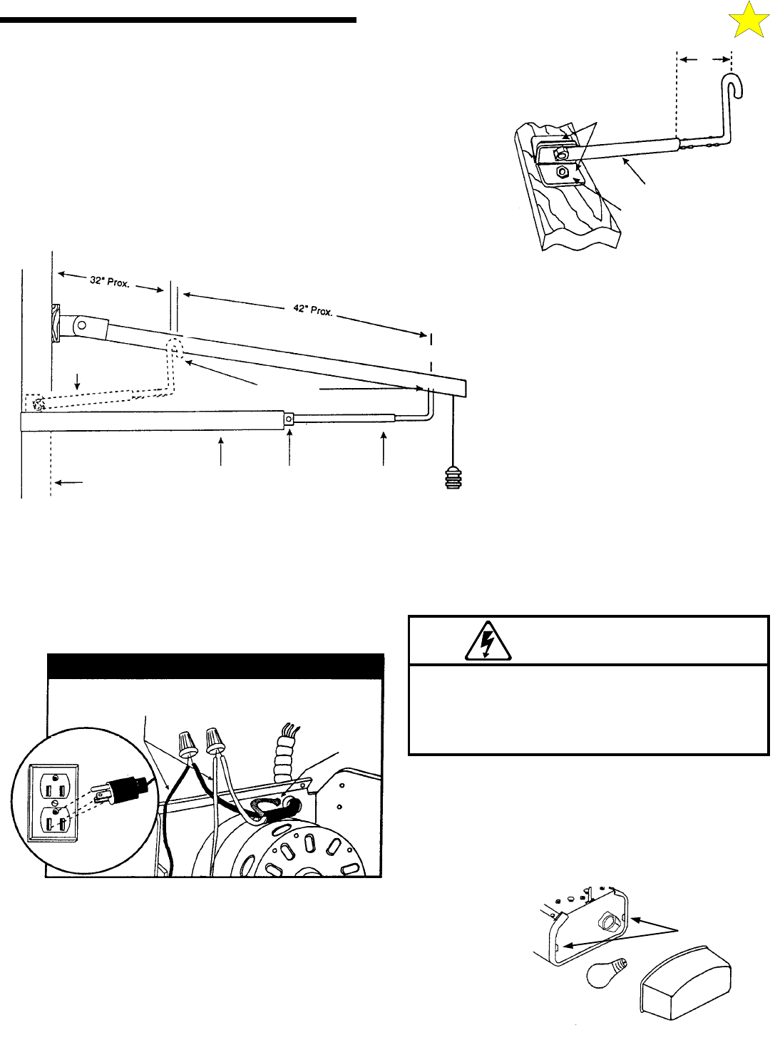
Step 10: Connecting the Door Arm to the Door - ONE PIECE
DOORS (USING OPTIONAL ONE PIECE DOOR ARM ASSEMBLY)
Attach door arm brackets to the top surface of the door on the center line.
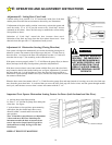
Reposition Open and Close limit stops so trolley stops in locations as shown.
Assemble the door arm by screwing curved rod into straight tube section. Allow
approximately 6” of rod to project outside of the straight tube.
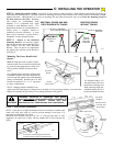
Release trolley with red knob handle and move to a convenient position between
Open and Close limits. Connect curved rod
section to trolley.
Slide door arm and trolley toward door; connect
the tube assembly to the door bracket with the
3/8” diameter bolt and locking nut, tightening
enough to allow for door arm pivot. Do not
overtighten the locking nut.
Press door control button and run opener through
full open and close cycles, adjusting the limit
stops as required to fully open and close the
door. At full closed position, the door arm
assembly should compress approximately one
inch.
110055-1
Closed Limit
Stop Location
Open Limit
Stop Location
Fully Open
Fully Closed
Trolley
Door Arm
Connection
Door Arm Door Arm Bracket Open Door
Closed Door
Door Arm
Door
Brackets
Straight Tube
Bolt/Nut
6”
110054-2
IMPROPER WIRING COULD CAUSE
ELECTROCUTION OR DAMAGE TO
CIRCUITRY. FOLLOW LOCAL BUILDING
AND ELECTRICAL CODES.
WARNING
WARNINGWARNING
WARNING