


10
C: INSTALLING THE OPERATOR
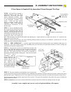
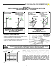
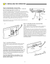
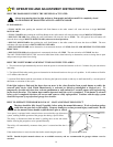
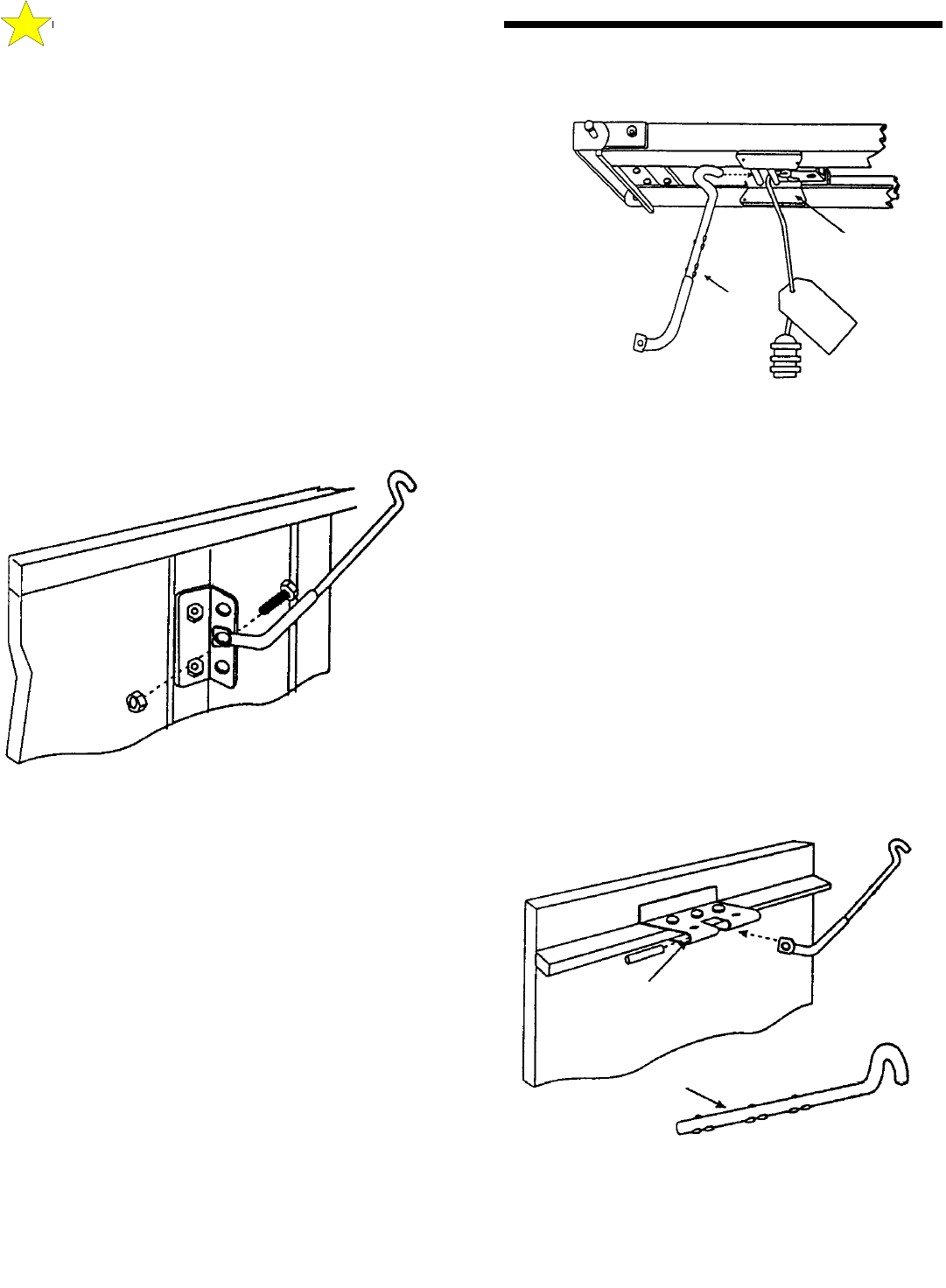
Step 8: Connecting Door Arm to Trolley
(THIS IS FOR SECTIONAL DOORS ONLY - FOR ONE
PIECE DOORS PROCEED TO STEP 10)
The door arm assembly consists of the door arm tube section and door arm
rod which are packaged separately. To assemble, screw the door arm rod into
the the door arm tube in a clockwise direction approximately ten turns.
Connect the door arm assembly into the trolley with the open end of the rod
hook facing the power head unit (away from the door). Extend the manual
release cord (connected to the trolley) and thread through the warning tag and
red pull knob handle. Adjust so the knob is 6 feet above the floor and secure
with a double overhand knot in the end of the release cord.
Release the trolley (leave door arm attached) with the manual release cord
and pull trolley toward the door.
110053-2
Trolley
(Close Limit Position)
Cushion
Arm
Assembly
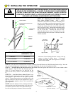
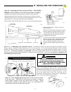
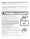
Step 9: Connecting the Door Arm to the Door
Type 1: Door Mounted Bracket
Visually align the door arm connecting hole with the middle hole of
the door bracket by rotating the tube section in the appropriate
direction.
Release the trolley (leave door arm attached) with the manual release
cord and pull trolley toward the power head unit. Now rotate the door
arm tube section two turns counterclockwise (increasing the exposed
length of the door rod) to provide a cushion when the door is closed or
encounters an obstruction. Align connecting hole in the door arm to
middle hole in the door bracket; insert 3/8” diameter bolt and tighten
locking nut, allowing for free pivot of the arm. Note: Do not
overtighten locking nut as this will cause binding between the door
arm and door bracket.
110054-2
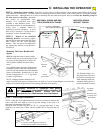
Type 2: Strut Mounted Bracket
Visually align the door arm connecting hole with the connecting
pin of the strut by rotating the tube section in the appropriate
direction.
Release the trolley (leave door arm attached) with the manual
release cord and pull trolley toward the power head unit. Now
rotate the door arm tube section two turns counterclockwise
(increasing the exposed length of the door rod) to provide a cushion
when the door is closed or encounters an obstruction. Align
connecting hole in the door arm with the strut mounted connecting
bracket. Insert connecting pin through the hole in the door arm.
Secure the connecting pin to the strut bracket according to the
manufacturer’s instructions.
Note: Door Bracket Mount or Strut Mount - If rod
bottoms in cushion tube, cut rod to allow for proper
function of this assembly.
Alternate Strut
Connecting Bracket
Cut to Fit
110054-2