


© Copyright, Alliance Laundry Systems LLC – DO NOT COPY or TRANSMIT
Installation
F232085
36
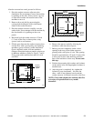
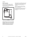
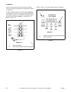
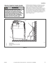
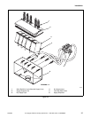
On U4 and earlier model units, a stainless steel box at
the right rear of the control module houses a terminal
strip which furnishes supply output signals for the
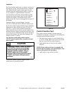
chemical injection supply pumps. Refer to Figure 19
for an example of a typical terminal strip decal.
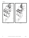
On U5 and later model units, the terminal strip that
furnishes the supply output signal for the chemicals
injection and supply is located inside the control
module at the rear. Access is through the rear panel of
the module.
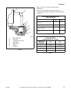
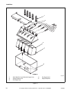
Terminals Supply 1 through Supply 5 provide
120 VAC or 240 VAC fused at 500 mA. (Refer to the
decal at the external supply terminal strip to determine
whether the washer-extractor provides 120 VAC or
240 VAC, as well as other pertinent information.)
These terminals may be used to provide signals to the
chemical injection supply system but must not be used
to provide power to the actual pump. Do not attempt to
increase fuse rating as this may cause damage to the
washer-extractor’s circuitry.
Any injection system pump which requires
110 VAC must be powered by a separate external
power source.
Consult the chemical injection supply system
instructions for operational details.
Figure 19
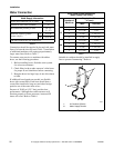
Control Function Test
The washer-extractor should be cleaned after the
installation is complete. A function test should then be
executed on the unloaded machine:
1. Check the power supply for such characteristics
as correct voltage, phase, and cycles to be certain
they are correct for the washer-extractor.
2. Open manual shut-off valves to the washer-
extractor.
NOTE: If the washer-extractor is equipped with
the WE-6 microcomputer, press the emergency stop
button at this point in the procedure.
3. Apply power to the washer-extractor.
Attempting to obtain 110VAC by using L1
or L2 with the common may damage
laundry machine circuitry and/or the
chemical injection system. Using a
240VAC power wire in the washer-
extractor and an earth ground to obtain
110VAC could cause microprocessor
problems.
SW028
CAUTION
P043I
F3A
F10A MAX
NEUTRAL TO SPLY 1 THRU SPLY 5 YIELDS 120VAC
P/N 230764 -1
LINE 1
LINE 2
NEUTRAL
SUPPLY 1
SUPPLY 2
SUPPLY 3
SUPPLY 4
SUPPLY 5