


© Copyright, Alliance Laundry Systems LLC – DO NOT COPY or TRANSMIT
Installation
23
F232085
After the concrete has cured, proceed as follows:
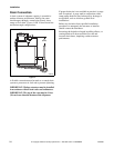
1. Place the washer-extractor adjacent to the
foundation. Do not attempt to move the machine
by pushing on the sides. Always insert a pry bar
or other device under the bottom frame of the
machine to move it.
2. Remove the wood skid by unscrewing the
carriage bolts holding the skid to the bottom
frame of the washer-extractor.
3. Place the washer-extractor carefully over the
anchor bolts. Never attempt to lift the machine by
the door handle or by pushing on the cover
panels.
4. Raise and level the washer-extractor 1/2 inch
(1.3 cm) off the floor on three points, using
spacers such as nut fasteners.
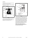
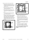
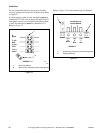
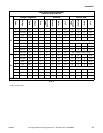
5. Fill the space between the washer-extractor base
and the floor with a good quality non-shrinking
machinery grout to ensure a stable installation.
Grout completely under all frame members.
(Remove front panel and rear panel to gain access
to all frame members.) Refer to Figures 7 and 8.
Force grout under machine base until all voids
are filled.
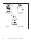
Figure 7
6. Remove the spacers carefully, allowing the
machine to settle into the wet grout.
7. Before grout sets completely, make a drain
opening in the rear of the washer-extractor
grouting with a stiff piece of wire. This opening
should be approximately 1/2 inch (13 mm) wide
to allow any surface water build-up under the
base of the machine to drain away. Do not omit
this step.
8. Position the mounting bolt washers and locknuts
on the anchor bolts and fingertighten locknuts to
machine base.
9. After the grout is completely dry, tighten the
locknuts by even increments – one after the
other – until all are tightened evenly and the
washer-extractor is fastened securely to the floor.
NOTE: Check and retighten the locknuts after five
to ten days of operation and every month
thereafter.
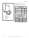
PHM547N
PHM547N
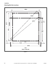
UW35
22-3/8 in.
(568 mm)
30-1/2 in.
(775 mm)
22 in.
(559 mm)
4-1/16 in.
(103 mm)
Typical
4-1/16 in.
(103 mm)
Typical
30-1/8 in.
(765 mm)
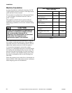
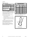
PHM548N
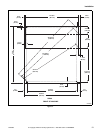
Figure 8
PHM548N
UW60
36 in.
(914 mm)
27-1/2 in.
(699 mm)
27-7/8 in.
(708 mm)
35-5/8 in.
(905 mm)
4-1/16 in.
(103 mm)
Typical
4-1/16 in.
(103 mm)
Typical