


29 Chapter 3
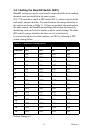
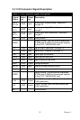
3.3.1 I/O Connector Signal Description
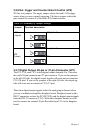
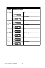
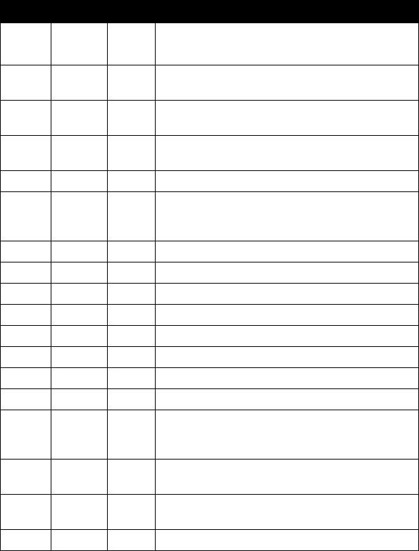
Table 3.9: I/O Connector Signal Descriptions
Signal
Name
Refere
nce
Direct
ion
Description
A/D S
<0..15>
A.GND Input
Analog input (single-ended), channels 0
through 15.
A/D H
<0..7>
A.GND Input
Analog input high (differential), channels 0
through 7.
A/D L
<0..7>
A.GND Input
Analog input low (differential), channels 0
through 7.
D/A A.GND Output Analog output
AGND - -
Analog Ground. The two ground references
(A.GND and D.GND) are connected together
on the PCI-1718HDU/HGU card.
D/O D.GND Output Digital output, channels 0 through 15.
D/I D.GND Input Digital input, channels 0 through 15.
CLK D.GND Input Clock input for the 8254.
GATE D.GND Input Gate input for the 8254.
OUT D.GND Output Signal output for the 8254.
VREF D.GND Output Voltage reference.
REFIN D.GND Input External voltage reference input.
S1-S4 D.GND Output Daughterboard channel select.
DGND - -
Digital Ground. The two ground references
(A.GND and D.GND) are connected together
on the PCI-1718HDU/HGU card.
+12V D.GND Output
+12 VDC Source (from ISA bus directly with
FUSE protection).
+5V D.GND Output
+5 VDC Source (from ISA bus directly with
FUSE protection).
NC - - No connection.