


Watson-Marlow 620DuN and 620Du User Manual 71
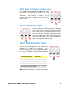
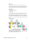
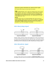
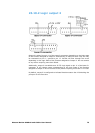
23.5 Run/stop input
Remote run/stop: connect a remote switch between pins 7 and 19 of the lower D-
connector. Alternatively a logic input may be applied to pin 7 of the lower D-connec-
tor, ground to pin 18. High input stops the pump, low input runs the pump. With no
connection or with the switch open, the pump will default to running. To change or
set the sense of the run/stop input, see 18.11 Remote stop in the Setup menu.
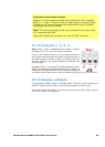
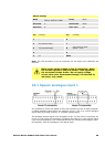
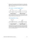
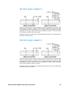
23.6 Direction input
To enable remote direction control and disable the DIRECTION (SHIFT, 1) key on
the keypad, link pins 6 and 18 of the lower D-connector. Connect a remote switch
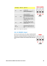
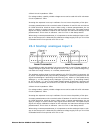
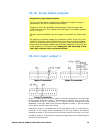
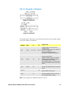
Important: general instructions for remote control inputs
All remote control inputs can be wired in two ways:
Logic
A logic voltage between 5V TTL and 24V industrial logic may be wired
to the input pin. The pump is configured to operate without modifica-
tion anywhere in this range. Any of the 0V pins is connected to the
control device’s 0V to make the circuit. One 0V pin is identified in the
wiring diagram, but any may be used. Low is equivalent to 0V. High
is equivalent to 5V→24V.
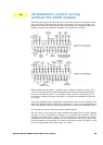
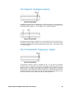
Switch
A remote switch may be connected between the input pin and any
positive voltage supply from the pump. One 5V supply pin is identified
in the wiring diagram but there are several which will do, either 5V or
other positive voltage. However, do not use pin 21 on the lower D-
connector or pin 20 on the upper D-connector.