


Watson-Marlow 620DuN and 620Du User Manual 63
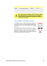
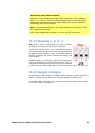
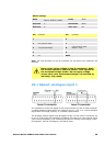
22.9 Auto / manual toggle input
Connect a remote switch between the +5V terminal and the
i/p terminal of the Auto-man i/p connector (J1). Closed
switch for automatic control; open switch for manual control.
Alternatively a logic input may be applied to the i/p
terminal of the Auto-man i/p connector, ground to the 0V
terminal. High input for automatic control; low input for
manual control.
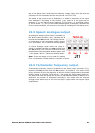
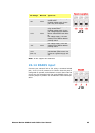
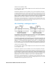
22.10 MemoDose input
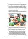
Connect a momentary contact switch such as a footswitch
or a handswitch between the 5V terminal and the i/p ter-
minal of the Dose i/p connector (J3). Close the switch to
begin a dose. This input is software-debounced and func-
tions in a similar way to the other remote inputs, such as
with 5V to 24V logic as shown above, using the i/p ter-
minal and the 0V terminal. Note: This input is software-
debounced, so the signal can be either momentary or
maintained during the dose. If maintained, the signal
must be removed before the next dose.
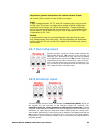
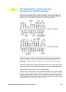
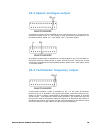
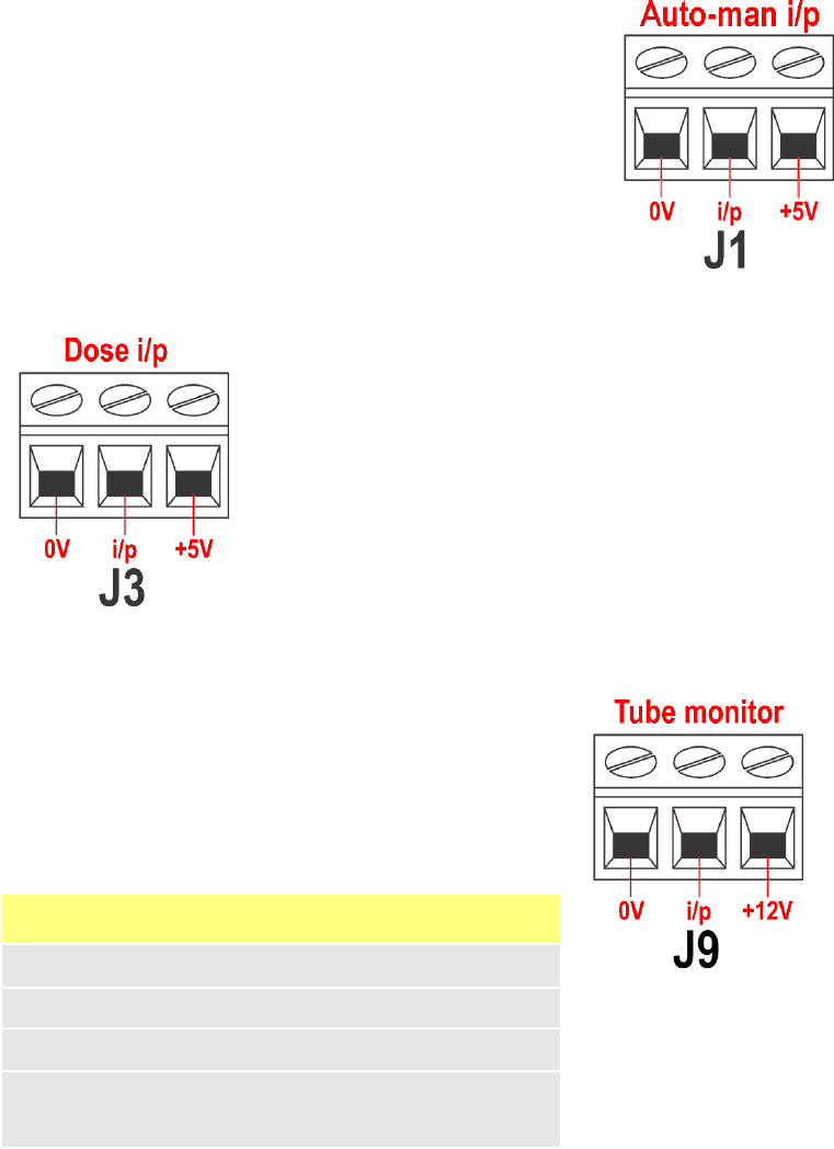
22.11 Leak detection input
Connect a remote leak-detection device between the
+12V terminal and the i/p terminal on the Tube monitor
connector (J9). Closed circuit indicates a leak.
Alternatively a logic input may be applied to the i/p ter-
minal, ground to the 0V terminal. High input indicates a
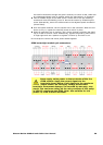
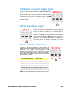
leak. Connect the cable of a Watson-Marlow Tube monitor
leak detector as follows:
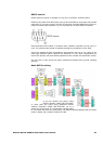
Note: Use only Watson-Marlow 620 series tube monitors.
Tube monitor wire colour 620N module
Blue J9 0V terminal
Yellow J9 i/p terminal
Red J9 +12V terminal
Terminate the screen in the 620N module with a 360° EMC
gland if required. See 22.2 Wiring up.