


Watson-Marlow 620DuN and 620Du User Manual 62
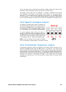
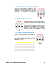
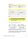
22.7 Run/stop input
Remote run/stop: connect a remote switch between the
i/p terminal and the +5V terminal of the Run/stop i/p
connector (J4). Alternatively a logic input may be applied
to the i/p terminal, ground to the 0V terminal. High input
stops the pump, low input runs the pump. With no connec-
tion or with the switch open, the pump will default to run-
ning. To change or set the sense of the run/stop input, see
18.11 Remote stop in the Setup menu.
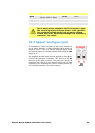
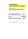
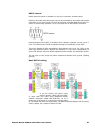
22.8 Direction input
To enable remote direction control and disable the DIRECTION (SHIFT, 1) key on
the keypad, link the terminals of the Direction enable link connector (J6).
Important: Apply no voltage whatever to the Direction enable link. Connect
a remote switch between the +5V terminal and the i/p terminal of the Direction i/p
connector (J2). Open switch for clockwise rotation, closed switch for counter-clock-
wise rotation. Alternatively a logic signal may be applied to the i/p terminal and the
0V terminal of the Direction i/p connector (J2). Low input for clockwise rotation,
high input for counter-clockwise rotation. With no connection the pump defaults to
clockwise rotation.
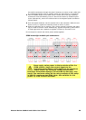
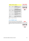
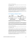
Important: general instructions for remote control inputs
All remote control inputs can be wired in two ways:
Logic
A logic voltage between 5V TTL and 24V industrial logic may be wired
to the input. The pump is configured to operate without modification
anywhere in this range. Any of the 0V terminals - though preferably
the 0V terminal associated with the desired input - is connected to the
control device’s 0V to make the circuit. Low is equivalent to 0V. High
is equivalent to 5V→24V.
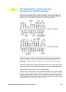
Switch
A remote switch may be connected between the input and any posi-
tive voltage supply from the pump - though preferably the associated
supply terminal. Do not use the 10V supply from the Rem-pot connec-
tor, however.