


Watson-Marlow 620DuN and 620Du User Manual 60
4-20mA circuit impedance: 250Ω.
For voltage modes, a stable, reliable voltage source can be used with a DC voltmeter.
Circuit impedance: 22kΩ.
Inverting the response is set up in software. Do not invert the polarity of the termi-
nals.
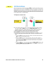
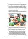
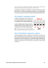
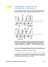
A remote potentiometer with a
nominal value of between 1k and
2k with a minimum of 0.25W
should be wired between the
terminals of the Rem-pot connec-
tor (J7) and the i/p terminal of
the Analogue 1 connector (J5).
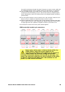
When using a remote potentiometer, do not apply a voltage
or current control input signal at the same time. The speed
control signal will require calibration relative to the minimum
and maximum settings of the potentiometer. This is done in
software. See 18.1 Trim in the Setup section.
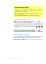
When using a remote potentiometer, it is important to set the analogue input to volt-
age in the Setup menu. Otherwise the reference voltage supply from the Rem-pot
connector will be overloaded and will not provide a full 5V or 10V.
22.4 Scaling: analogue input
It is possible to scale the speed of the pump remotely by one
of these methods: a voltage analogue signal within the
ranges 0-10V or 1-5V; or a current analogue signal within
the range 4-20mA; or a remote potentiometer using the 10V
supply at J7.
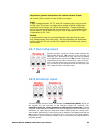
The analogue process signal must be applied to the i/p ter-
minal of the Analogue 2 connector (J8). Ground to the 0V
terminal of the same connector.
4-20mA circuit impedance: 250Ω.
For voltage modes, a stable, reliable voltage source can be used with a DC voltmeter.
Circuit impedance: 22kΩ.
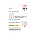
Inverting the response is set up in software. Do not invert the polarity of the
terminals.
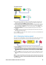
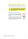
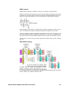
A remote potentiometer with a
nominal value of between 1k and
2k with a minimum of 0.25W
should be wired between the ter-
minals of the Rem-pot connector
(J7) and the i/p terminal of the
Analogue 2 connector (J8). When
using a remote potentiometer, do not apply a voltage or cur-
rent control input signal at the same time. The scaling con-
trol signal will require calibration relative to the minimum
and maximum settings of the potentiometer. This is done in
software - see 18.1 Trim in the Setup section.
When using a remote potentiometer, it is important to set the analogue input to volt-