


Watson-Marlow 620DuN and 620Du User Manual 64
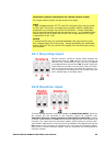
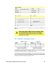
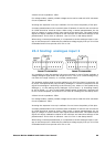
22.12 Outputs 1, 2, 3, 4
Note: Relay 1 (J14) is represented here. Relay 2, Relay 3
and Relay 4 (J15, J16 and J17) function identically.
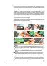
Connect your output device to the c (common) terminal of
your chosen relay connector and either the n/c terminal or
the n/o terminal (normally closed or normally open) as
required. Configure the pump’s software accordingly. See
18.10 Outputs.
By default, Relay 1 is configured to indicate Run/Stop status;
Relay 2 is configured to indicate Direction status; Relay 3 is
configured to indicate Auto/man status; Relay 4 is configured
to indicate General alarm status. See 12 Switching the pump on for the first time.
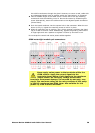
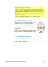
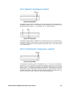
22.13 Supply voltages
An appropriate voltage supply is available where required on each connector. In
addition, supplies may be drawn from the Spare supplies connector (J12).
In the table below, “Max load” is the maximum total load on each supply, irrespec-
tive of the number of connections.
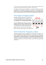
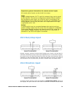
Important: pump status outputs
Outputs 1-4 are available as single-pole change-over relay contacts:
Relay 1, 2, 3 and 4. Connect to the normally open or normally closed
contacts of the relay as required and configure the pump’s software
accordingly. See 18.10 Outputs.
Note: The maximum rating on the relay contacts of this pump is 30V
DC; maximum load 30W.
Note: Also suitable for low power: ie, 1mA at 5VDC minimum.