


Watson-Marlow 620DuN and 620Du User Manual 106
ment over the 625L clamping peg. Stretch the tubes and screw the clamping
block into place. Replace the track as described at 33.4 620L removal and
installation.
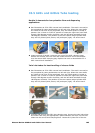
Two independent tubes for twin-channel pumping
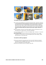
See illustrations at 33.4 620L removal and installation. The track is secured to
the pumphead by cams positioned at its left and right. Where the cam shafts
are visible at the front of the pumphead, they are milled square to accept a
spanner. Use a 10mm or 3/8in AF spanner to rotate the right-hand cam shaft
through 180 degrees counter-clockwise, and the left-hand camshaft through
180 degrees clockwise. The position of the cam rotation stops indicate when
they are fully closed (third picture, left) and open (right). Lift off the track.
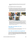
Unscrew and remove the 625L clamping pegs. Clamping blocks will be used to
secure the continuous tube, using the same screw sockets. Fit the two tubes
into the correct size clamping blocks. Distance between blocks = 230mm for up
to 8.0mm bore; 240mm for 12.0mm and 16.0mm bore. Fit the inlet tube
clamping block to the 625L. Stretch the tubes over the rotor and fit the second
tube clamping block to the 625L. Replace the track as described at 33.4 620L
removal and installation. When using Marprene it is important to check the tube
length after 30 minutes running time.
33.6 620L and 620LG care and
maintenance
Check all moving parts for freedom of movement occasionally. If aggressive fluids
are spilt onto the pumphead, clean using a mild detergent only.
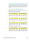
33.7 620L and 620LG track adjustment
The track is set for 4.0mm wall tubing up to 16.0mm bore. Alteration of this setting
using the pan head screws may be necessary to optimise performance if non-stan-
dard tubing is used. However, the pump warranty will be invalidated if this is
done. The factory setting is 20.3mm vertically from the rotor side of the sprung
track to the top of the track cover.