


Watson-Marlow 620DuN and 620Du User Manual 33
When the pump is under remote control, it tracks an analogue signal from the user’s
remote control system to the i/p terminal of the Analogue 1 and Analogue 2 con-
nectors at the rear of the pump within the ranges 4-20mA, 0-10V or 1-5V. The Trim
setup sequence allows the user to customise the process-signal-to-pump-speed cal-
ibration. The sequence may be entered directly from the Setup menu or from the
Analogue setup menu.
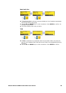
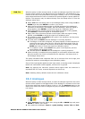
Select Trim from the Setup menu or the Analogue setup menu using the UP or
DOWN keys and press ENTER to confirm your choice.
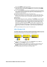
Apply the low process analogue signal to the i/p terminal of the Analogue 1
connector as instructed in the display. See 18.2 Analogue. While the signal is
being applied, press ENTER to record the signal as a calibration point.
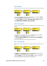
Apply the maximum process control signal. While the signal is being applied,
press ENTER to record the signal as a calibration point.
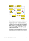
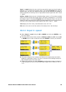
Apply 50% of the maximum process control signal. While the signal is being
applied, press ENTER to record the signal as a calibration point.
If a mistake is made, press STOP at any point in the sequence, and the pump
displays the previous screen.
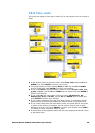
The final press on ENTER ends the Analogue 1 trimming sequence.
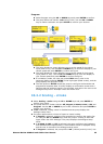
If Analogue 2 has been configured, the pump displays a similar sequence of
screens for that input. Apply the low, high and mid-range signal to the i/p
terminal of the Analogue 2 connector as instructed in the display, pressing
ENTER each time to record the signals as calibration points.
If a mistake is made, press STOP at any point in the sequence, and the
pump displays the previous screen.
The final press on ENTER ends the Analogue 2 trimming sequence.
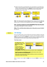
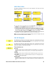
When trimming is complete the pump displays a confirmation screen and redis-
plays the screen from which it entered the trim sequence: the Setup menu or
the Analogue setup menu.
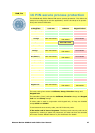
The pump calculates linear responses from low to mid and from mid to high, and
records the results as new analogue input calibration graphs.
If any of the three signals applied to each input match, a warning screen is displayed
before the confirmation screen appears, and the trim is ignored.
Note: By applying the maximum process control signal when the minimum is
requested and vice versa, inverted responses can be set up.
Note: Resetting factory defaults clears the trim calibration values.
18.2 Analogue
When the pump is under remote control, it tracks an analogue signal from the user’s
remote control system to the i/p terminal of the Analogue 1 connector at the rear
of the pump within the ranges 4-20mA, 0-10V or 1-5V. The Analogue option in the
Setup menu allows the user to configure the pump to operate with his remote con-
trol system.
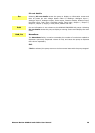
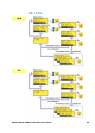
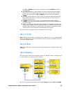
Select Analogue from the Setup menu using the UP or DOWN keys and press
ENTER to confirm your choice.
Four options are displayed: Input 1 - speed, Scaling - stroke, Trim and Exit.
DuN, Du