


Appendix A: Connector and Pinout Specifications
32 X-Series Hardware Installation and Safety Guide V 2.5
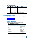
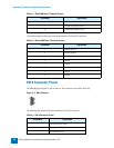
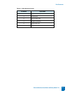
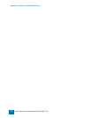
.The following table describes the pinout information for a 10/100 RJ-45 connector.
DB-9 Connector Pinout
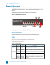
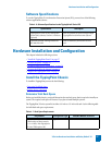
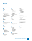
The following figure displays a -DB-9 connector. This connector is used in the X505 only.
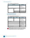
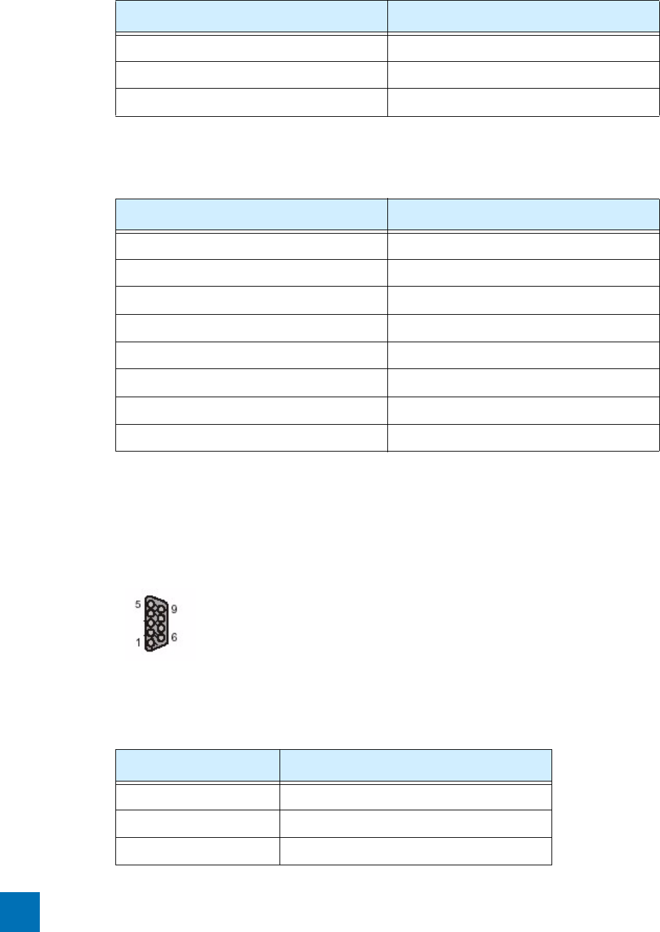
The following table details the pinout information for the DB-9 connector.
6 Twisted Pair 2 negative (TP2-)
7 Twisted Pair 4 positive (TP4+)
8 Twisted Pair 4 negative (TP4-)
Table A - 2: RJ-45 10/100 Base-T Connector Pinouts
Pin Number Signal Name
1Transmit positive
2 Transmit negative
3 Receive positive
4Unused
5Unused
6 Receive negative
7Unused
8Unused
Figure A - 2: DB-9 Connector
Table A - 3: DB-9 Connector Pinouts
Pin Number Signal Name
1 Data Carrier Detect (DCD)
2 Receive Data (RxD)
3Transmit Data (TxD)
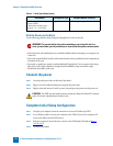
Table A - 1: RJ-45 1000 Base-T Connector Pinouts
Pin Number Signal Name