


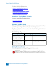

Hardware Installation and Configuration
X-Series Hardware Installation and Safety Guide V 2.5 27
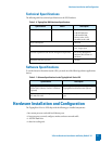
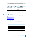
Software Specifications
To run the TippingPoint X-SeriesIntrusion Prevention System (IPS), you need one of the following
software applications/devices.
Hardware Installation and Configuration
This chapter includes the following sections:
• “
Install the TippingPoint Chassis” on page 27
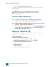
• “Connect the power” on page 28
• “Complete Initial Setup Configuration” on page 28
• “Connect the X506 to the Internet” on page 29
• “Register the TippingPoint X506” on page 30
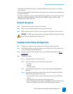
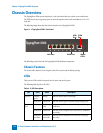
Install the TippingPoint Chassis
To install the TippingPoint you must do the following:
• Determine Total Rack Space
• Bolt the Device to the Rack
Determine Total Rack Space
Before you install the chassis, you should determine the total rack space that is required to install your
system. The required rack space will increase if you plan to install multiple systems.
The TippingPoint X-Series system fits in either a 19-inch or a 23-inch wide rack. See the following table
for individual rack space requirements.
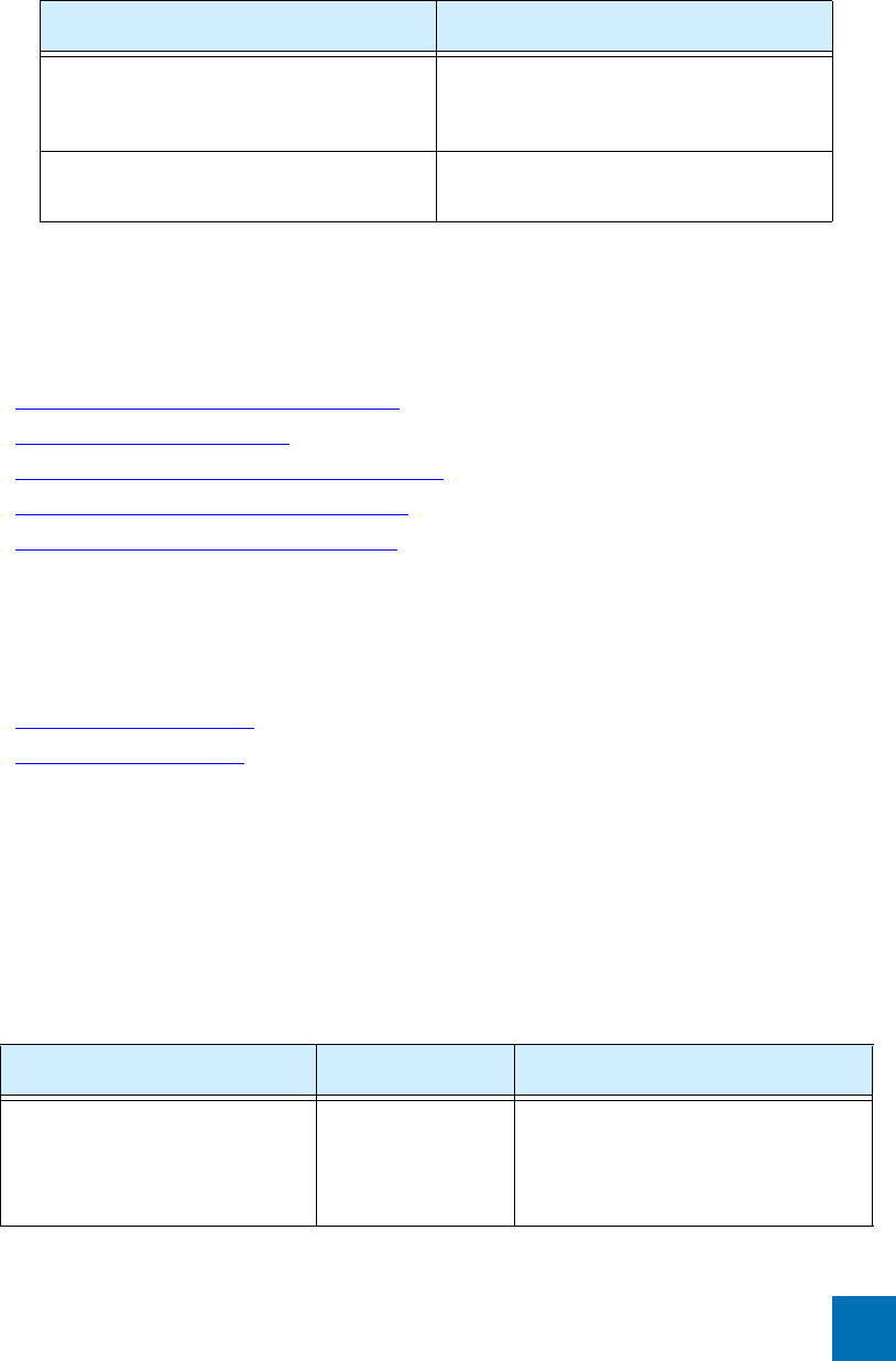
Table 4 - 6: Software Specifications for the TippingPoint X-Series IPS
Specification Description
TippingPoint X-Series Security Management
System (SMS) Software, Version 2.5 and above.
(optional)
SMS can optionally be used to manage multiple
TippingPoint Intrusion Prevention Systems.
1 Windows-based PC running Windows 9x,
NT, 2000, XP, or ME
Must be attached to your network via serial
port.
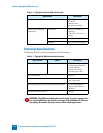
Table 4 - 7: Rack Space Requirements
Requirement Configuration Type Min/Max Number of Chassis
Physical Size of Rack
(Total number of chassis must be
< or = 42 RUs). Each TippingPoint
X-Series
X506 requires 1RU.
Typical Maximum of 9 chassis on a 7-foot rack.