


A
X-Series Hardware Installation and Safety Guide V 2.5 31
Connector and Pinout
Specifications
This appendix provides connector and pinout information for the TippingPoint X-Series X-Series
systems.
Port Connectors
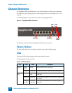
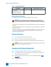
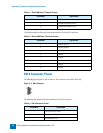
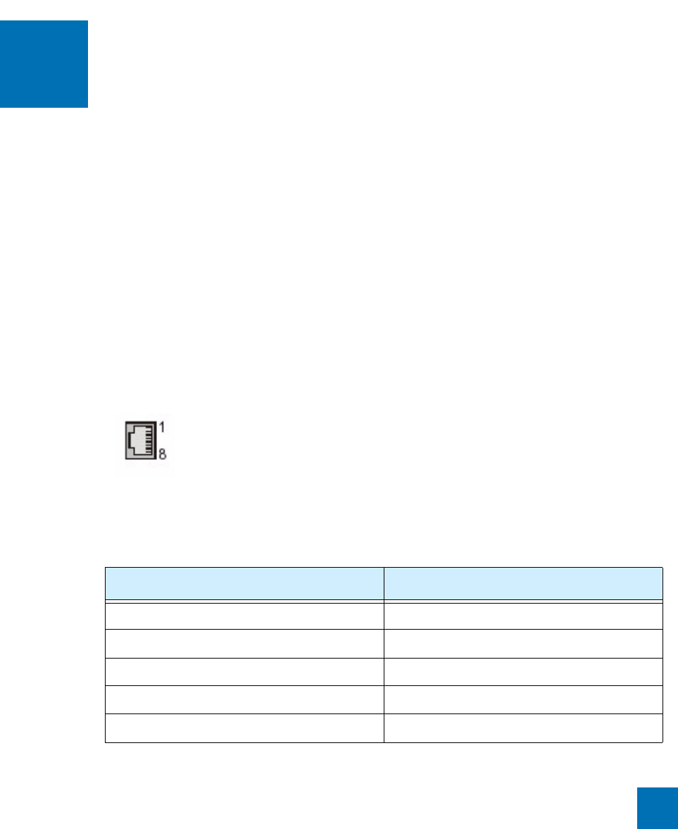
The TippingPoint X-Series supports the RJ-45 connectors, which have pinouts shown below.
The following figure displays an RJ-45 connector.
The following table describes the pinout information for a 1000 Base-T RJ-45 connector.
Figure A - 1: RJ-45 Connector
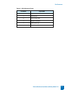
Table A - 1: RJ-45 1000 Base-T Connector Pinouts
Pin Number Signal Name
1 Twisted Pair 1 positive (TP1+)
2 Twisted Pair 1 negative (TP1-)
3 Twisted Pair 2 positive (TP2+)
4 Twisted Pair 3 positive (TP3+)
5 Twisted Pair 3 negative (TP3-)