


Chapter 3: TippingPoint X505 Overview
20 X-Series Hardware Installation and Safety Guide V 2.5
This chapter includes the following sections:
• “
Install the TippingPoint Chassis” on page 20
• “Connect the power” on page 21
• “Complete Initial Setup Configuration” on page 21
• “Connect the X505 to the Internet” on page 22
• “Register the TippingPoint X505” on page 22
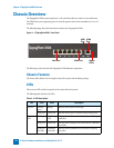
Install the TippingPoint Chassis
To install the TippingPoint you must do the following:
• Determine Total Rack Space
• Bolt the Device to the Rack
Determine Total Rack Space
Before you install the chassis, you should determine the total rack space that is required to install your
system. The required rack space will increase if you plan to install multiple systems.
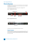
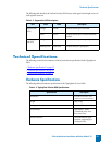
The X505 system fits in either a 19-inch or a 23-inch wide rack. See the following table for individual
rack space requirements.
Bolt the Device to the Rack
Use the following guidelines when bolting the TippingPoint X-Series to the rack:
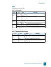
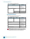
Table 3 - 8: Rack Space Requirements
Requirement Configuration Type Min/Max Number of Chassis
Physical Size of Rack
(Total number of chassis must be
< or = 42 RUs). Each TippingPoint
X-Series
X505 requires 1RU.
Typical Maximum of 9 chassis on a 7-foot rack.
Network Equipment Building
Systems (NEBS)
(Total number of chassis must
generate: < or = 1372 Watts)
Typical 13 chassis generating < or = 105 Watts
WARNING: To prevent bodily injury when mounting or servicing this unit in a
rack, you must take special precautions to ensure that the system remains stable.