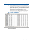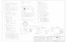
Meter to Flow Computer Communication Worksheet 330
Reference, Installation, and Operations Manual Meter setup and configuration worksheet
3-9000-743 Rev S June 2013
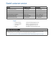
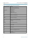
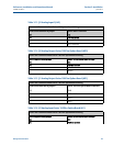
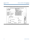
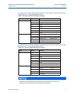
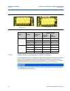
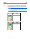
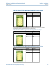
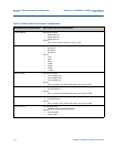
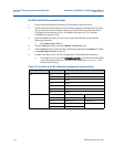
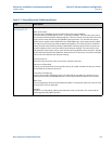
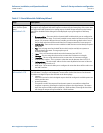
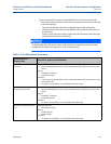
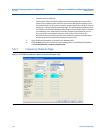
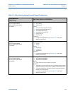
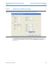
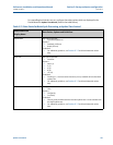
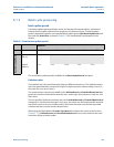
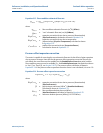
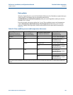
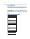
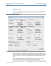
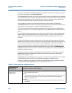
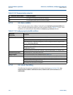
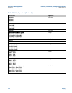
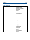
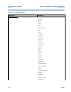
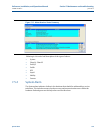
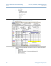
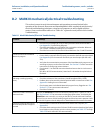
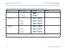
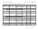
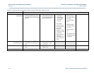
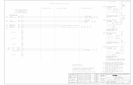
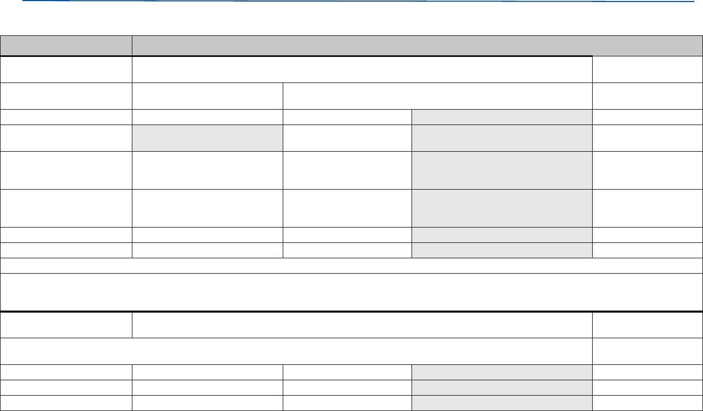
Analog Input
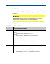
AI2 (Pressure)
User Selection (Circle one) Results (Enter Here)
Electrical Configuration • Sink • Source (i.e., powered by the meter) If the analog input is configured for
source mode, then it must be at the bottom of the loop (stack).
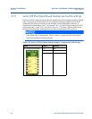
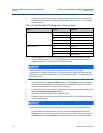
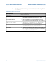
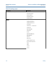
Pressure Type • gage • absolute
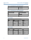
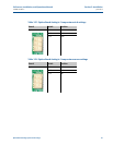
Atmospheric Pressure
(if absolute selected)
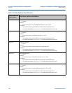
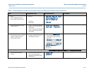
Minimum Input
(pressure corresponding to
4mA input)
• _____ psig
(if gage is selected)
• ______psia
(if absolute is selected)
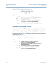
Maximum Input
(pressure corresponding to
20mA input)
• ______psig • ______psia
Low Alarm • ______psig • ______psia
High Alarm • ______psig • ______psia
Note: If the pressure is at or outside these limits, an alarm is generated
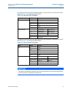
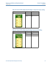
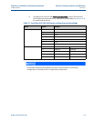
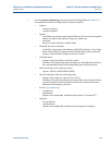
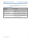
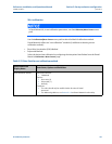
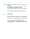
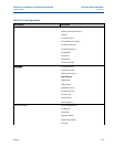
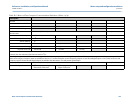
Note: Pressure is required for optional meter internal diameter Pressure expansion correction. If a pressure transmitter is connected to the meter, select Live for this option. If a
pressure transmitter is not connected to the meter but pressure expansion correction is required, select Fixed. You will enter in a fixed pressure on a later page. If the correction is
not required, select Not used.
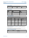
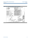
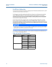
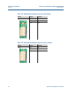
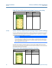
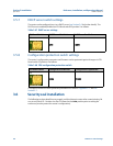
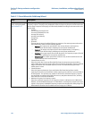
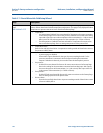
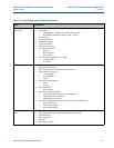
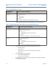
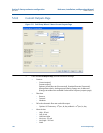
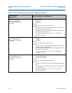
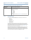
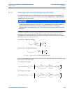
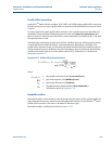
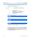
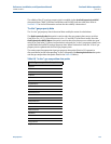
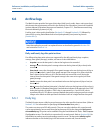
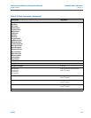
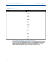
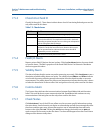
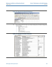
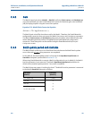
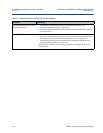
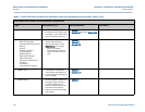
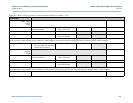
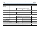
Digital Input
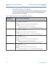
DI1
User Selection (Circle one) Results (Enter Here)
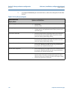
The Digital Input (DI1) may used to bring prover detector switches into the meter for “proving” against a ball prover (required only if input is used for
gated calibrations). Note: When using the digital method, the frequency output is not used for proving.
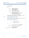
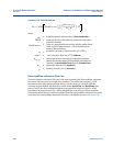
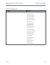
Calibration Type • Gated • Timed
Is DI1ForCalActiveLow • Active High • Active Low
Is DI1ForCalStateGated • Edge • State
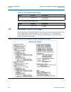
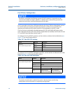
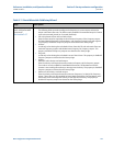
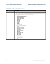
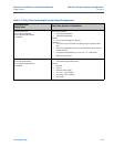
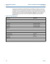
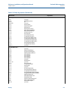
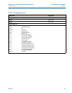
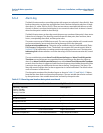
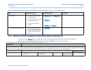
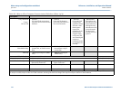
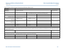
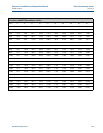
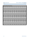
Table E-2 Meter to Flow Computer Communication Worksheet (Sheet 9 of 9)
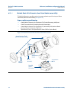
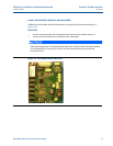
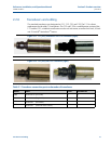
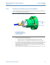
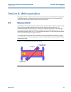
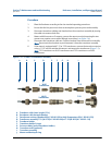
Description