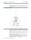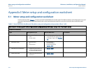
Meter setup and configuration worksheet Reference, Installation, and Operations Manual
June 2013 3-9000-743 Rev S
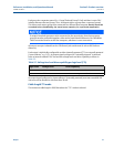
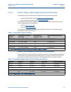
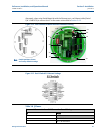
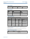
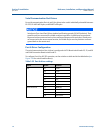
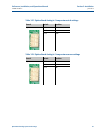
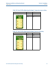
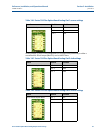
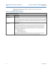
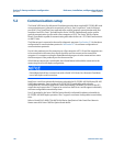
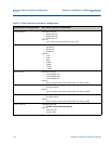
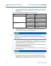
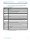
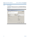
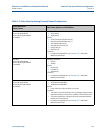
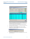
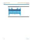
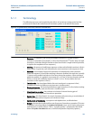
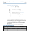
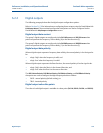
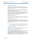
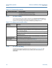
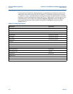
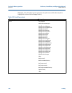
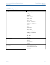
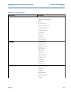
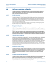
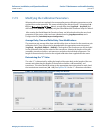
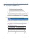
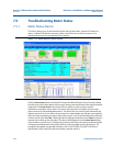
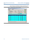
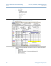
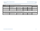
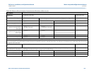
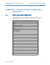
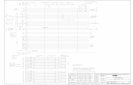
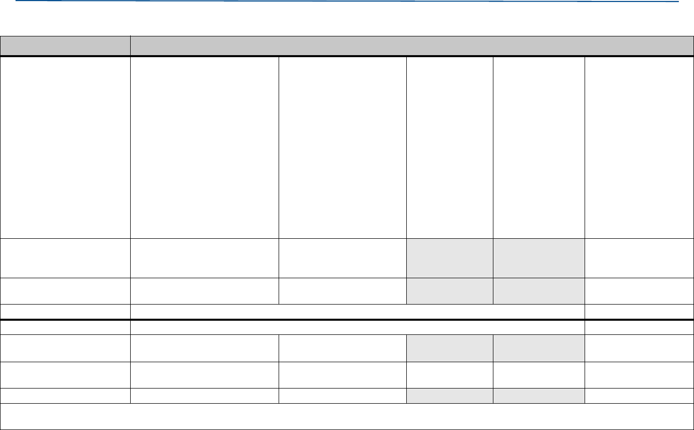
325 Meter to Flow Computer Communication Worksheet
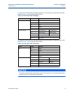
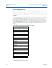
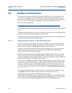
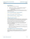
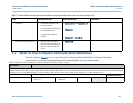
Freq 1 Direction
Group 1
FO1A, FO1B
• Forward:
FO1A and FO1B output pulses
only when flow is in the forward
direction.
• Reverse:
FO1A and FO1B output
pulses only when flow is in
the reverse direction.
• Absolute:
FO1A and FO1B
output pulses
regardless of flow
direction. Note:
Both outputs
report flow
regardless of the
flow direction.
Suggest config-
uring one of the
associated digital
outputs to
indicate direction
or use phase rela-
tionship.
• Bidirectional:
FO1A pulses only
when flow is in the
forward direction.
FO1B pulses only
when flow is in the
reverse direction.
The phase rela-
tionship setting is
ignored.
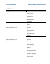
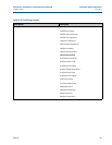
Freq B (FO1B
Phase Relationship
• FO1B lags FO1A by 90
O
if
forward flow, or leads if reverse
flow.
• FO1B leads FO1A by 90
O
if
forward flow, or lags if
reverse flow.
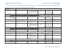
Max Freq • 1000 Hz (overrange to 1500Hz
max).
• 5000 Hz (overrange to
7500Hz max).
Full Scale Flow Rate Refer to note in Modbus volume and flow rate units section of this table
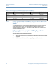
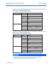
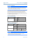
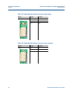
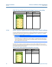
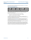
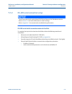
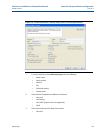
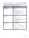
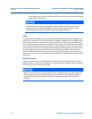
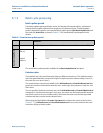
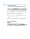
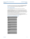
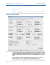
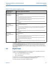
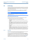
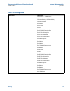
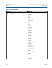
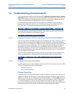
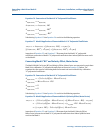
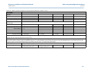
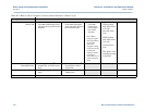
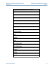
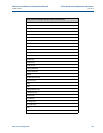
Digital Output Group 1 DO1A User Selection (Circle one) Results (Enter here)
Electrical Configuration • TTL
“Internally Powered”
• OC
“Open Collector”
Content • Flow Direction • Flow Validity
Polarity • Normal • Inverted*
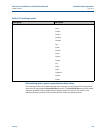
*Note: Inverted operation - use if the output of the meter is reversed from what a flow computer is expecting. Selecting the check box inverts the digital output. This means that if
the output normally outputs a HIGH for a TRUE condition, selecting this check box changes the output to output a LOW for a TRUE condition.
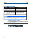
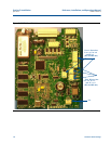
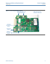
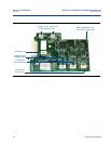
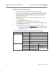
Table E-2 Meter to Flow Computer Communication Worksheet (Sheet 4 of 9)
Description