


50 YORK INTERNATIONAL
VACUUM TESTING
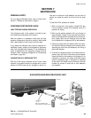
After the pressure test has been completed, the vacuum
test should be conducted as follows:
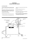
1. Connect a high capacity vacuum pump, with indi-
cator, to the system charging valve as shown in
Fig. 22 and start the pump. (See “Vacuum Dehydra-
tion”.)
2. Open wide all system valves, including the purge
and gauge valves. Be sure all valves to the atmo-
sphere are closed.
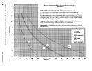
3. Operate the vacuum pump in accordance with
VACUUM DEHYDRATION until a wet bulb tempera-
ture of +32°F or a pressure of 5 mm Hg is reached.
See Table 3 for corresponding values of pressure.
4. To improve evacuation circulate hot water (not to
exceed 125°F) through the cooler and condenser
tubes to thoroughly dehydrate the shells. If a source
of hot water is not readily available, a portable wa-
ter heater should be employed. DO NOT USE
STEAM. A suggested method is to connect a hose
between the source of hot water under pressure
and the cooler head drain connection, out the cooler
vent connection, into the condenser head drain and
out the condenser vent. To avoid the possibility of
causing leaks, the temperature should be brought
up slowly so that the tubes and shell are heated
evenly.
5. Close the system charging valve and the stop valve
between the vacuum indicator and the vacuum
pump. Then disconnect the vacuum pump leaving
the vacuum indicator in place.
6. Hold the vacuum obtained in Step 3 in the system
for 8 hours; the slightest rise in pressure indicates
a leak or the presence of moisture, or both. If, after
8 hours the wet bulb temperature in the vacuum
indicator has not risen above 40°F or a pressure of
6.3 mm Hg, the system may be considered tight.
NOTE: Be sure the vacuum indicator is valved off
while holding the system vacuum and be
sure to open the valve between the vacuum
indicator and the system when checking
the vacuum after the 8 hour period.
7. If the vacuum does not hold for 8 hours within the
limits specified in Step 6 above, the leak must be
found and repaired.
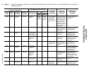
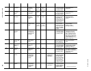
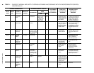
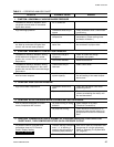
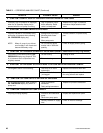
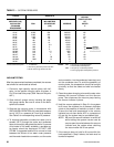
TABLE 3 – SYSTEM PRESSURES
*GAUGE ABSOLUTE
BOILING
INCHES OF TEMPERATURES
MERCURY (HG) MILLIMETERS OF
BELOW ONE PSIA OF MERCURY MICRONS WATER
STANDARD (HG) °F
ATMOSPHERE
0 14.696 760. 760,000 212
10.24" 9.629 500. 500,000 192
22.05" 3.865 200. 200,000 151
25.98" 1.935 100. 100,000 124
27.95" .968 50. 50,000 101
28.94" .481 25. 25,000 78
29.53" .192 10. 10,000 52
29.67" .122 6.3 6,300 40
29.72" .099 5. 5,000 35
29.842" .039 2. 2,000 15
29.882" .019 1.0 1,000 +1
29.901" .010 .5 500 –11
29.917" .002 .1 100 –38
29.919" .001 .05 50 –50
29.9206" .0002 .01 10 –70
29.921" 0 0 0
*One standard atmosphere = 14.696 PSIA
= 760 mm Hg. absolute pressure at 32°F
= 29.921 inches Hg. absolute at 32°F
NOTES: PSIA = Lbs. per sq. in. gauge pressure
= Pressure above atmosphere
PSIA = Lbs. per sq. in. absolute pressure
= Sum of gauge plus atmospheric pressure