


YORK INTERNATIONAL 41
FORM 160.49-O2
age to the Micro Board that represents this level (0% =
empty; 100% = full). Under program control, the Micro
Board modulates a variable orifice to control the con-
denser refrigerant level to a programmed setpoint. Other
setpoints affect the control sensitivity and response.
These setpoints must be entered at chiller commis-
sioning by a qualified service technician. Only a quali-
fied service technician may modify these settings.
Manual operation of the refrigerant level control can be
selected. This allows the prerotation vanes keypad keys
to manually control the variable orifice. This manual
control can also be used to position the variable orifice
in a fixed position. Instructions for selecting manual
level control and entering the level control setpoints
are contained in the “Special Setpoints and Program-
ming Procedures” section of Service manual, Form
160.49-M3.
While the chiller is shut down, the orifice will be in the
fully open position causing the sensed level to be ap-
proximately 0%. When the chiller is started, after the
vane motor end switch (VMS) opens when entering
“SYSTEM RUN”, if actual level is less than the level
setpoint, a linearly increasing ramp is applied to the
level setpoint. This ramp causes the setpoint to go from
the initial refrigerant level (approximately 0%) to the
programmed setpoint over a period of 15 minutes. While
this ramp is in effect,
PULLDN LEVEL = XXX%; SETP = XXX%; ACTUAL = XXX%
is
one of the scrolled messages under the DISPLAY DATA
key. “PULLDN LEVEL” is the ramping setpoint that will
ramp up to the programmed setpoint “SETP”. “SETP”
is the level setpoint programmed by the service tech-
nician. “ACTUAL” is the present refrigerant level in the
condenser. After the 15 minute pulldown period has
elapsed, this message is replaced by
ACTUAL LEVEL = XXX%; LEVEL SETP = XXX%
.
If the actual level is greater than the setpoint when the
VMS opens, there is no pulldown period, it immedi-
ately begins to control to the programmed setpoint.
While the chiller is running, the refrigerant level is nor-
mally controlled to the level setpoint. However, any-
time the vanes fully close (VMS closes), normal level
control is terminated, any refrigerant level setpoint
pulldown in effect is cancelled and the outputs to the
level control will be opposite that which is supplied to
the vane motor (i.e., when a close pulse is applied to
the vane motor, an open pulse is applied to the level
control, etc.). When the VMS opens, if the refrigerant
level is less than the level setpoint, a refrigerant level
setpoint pulldown is initiated as described above. Oth-
erwise, the level is controlled to the programmed
setpoint.
If the refrigerant level sensor output ever goes to greater
than 4.4VDC, indicating a level greater than 100%,
WARNING-REFRIGERANT LEVEL OUT OF RANGE
is dis-
played and the level control actuator is driven open
until the level has decreased to a level within range.
When within range, the warning message is automati-
cally cleared and normal control is resumed.
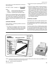
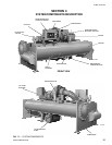
MICROCOMPUTER CONTROL CENTER
(See Section 2)
The MicroComputer Control Center is factory mounted,
wired and tested. The electronic panel automatically
controls the operation of the unit in meeting system
cooling requirements while minimizing energy usage.
For detailed information on the Control Center, refer to
“Section 2” of this manual.
SOLID STATE STARTER (Optional)
The Solid State Starter is a reduced voltage starter
that controls and maintains a constant current flow to
the motor during start-up. It is mounted on the chiller.
Power and control wiring between the starter and chiller
are factory installed. Available for 380-600 volts, the
starter enclosure is NEMA-1 with a hinged access door
with lock and key. Electrical lugs for incoming power
wiring are provided.
VARIABLE SPEED DRIVE (Optional)
A 460V – 3-Ph – 60/50Hz Variable Speed Drive can be
factory packaged with the chiller. It is designed to vary
the compressor motor speed and prerotation vane po-
sition by controlling the frequency and voltage of the
electrical power to the motor. Operational information
is contained in Form 160.00-O1. The control logic au-
tomatically adjusts motor speed and compressor
prerotation vane position for maximum part load effi-
ciency by analyzing information fed to it by sensors
located throughout the chiller.