


2 YORK INTERNATIONAL
TT
TT
T
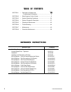
ABLE OF CONTENTSABLE OF CONTENTS
ABLE OF CONTENTSABLE OF CONTENTS
ABLE OF CONTENTS
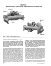
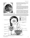
SECTION 1 – Description of System and
Fundamentals of Operation ......................................... 4
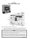
SECTION 2 – MicroComputer Control Center ...................................... 6
SECTION 3 – System Operating Procedures..................................... 30
SECTION 4 – System Component Description .................................. 37
SECTION 5 – Operational Maintenance ............................................. 42
SECTION 6 – Trouble Shooting........................................................... 44
SECTION 7 – Maintenance ................................................................. 49
SECTION 8 – Preventive Maintenance............................................... 58
REFERENCE INSTRREFERENCE INSTR
REFERENCE INSTRREFERENCE INSTR
REFERENCE INSTR
UCTIONSUCTIONS
UCTIONSUCTIONS
UCTIONS
DESCRIPTION FORM NO.
Solid State Starter – Operation & Maintenance 160.46-OM3.1
Variable Speed Drive – Operation 160.00-O1
Installation 160.49-N5
Installation and Operation of Printers 160.49-N7
Wiring Diagram – Unit with Electro-Mechanical Starter 160.49-PW7
Wiring Diagram – Field Connections (E-M Starter) 160.49-PW10
Wiring Diagram – Field Control Modifications 160.49-PW13
Wiring Diagram – Control Center with SS Starter 160.49-PW8
Wiring Diagram – Field Connections (SS Starter) 160.49-PW11
Wiring Diagram – Solid State Starter 160.49-PW14
Wiring Diagram – Unit with Solid State Starter 160.49-PW8
Wiring Diagram – Unit with Variable Speed Drive 160.49-PW9
Wiring Diagram – Field Connections (V.S.D.) 160.49-PW12
Wiring Diagram – Variable Speed Drive 160.49-PW15
Page