


4 YORK INTERNATIONAL
SECTION 1
DESCRIPTION OF SYSTEM AND FUNDAMENTALS OF OPERATION
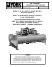
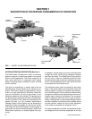
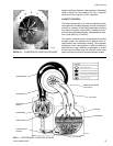
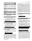
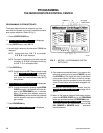
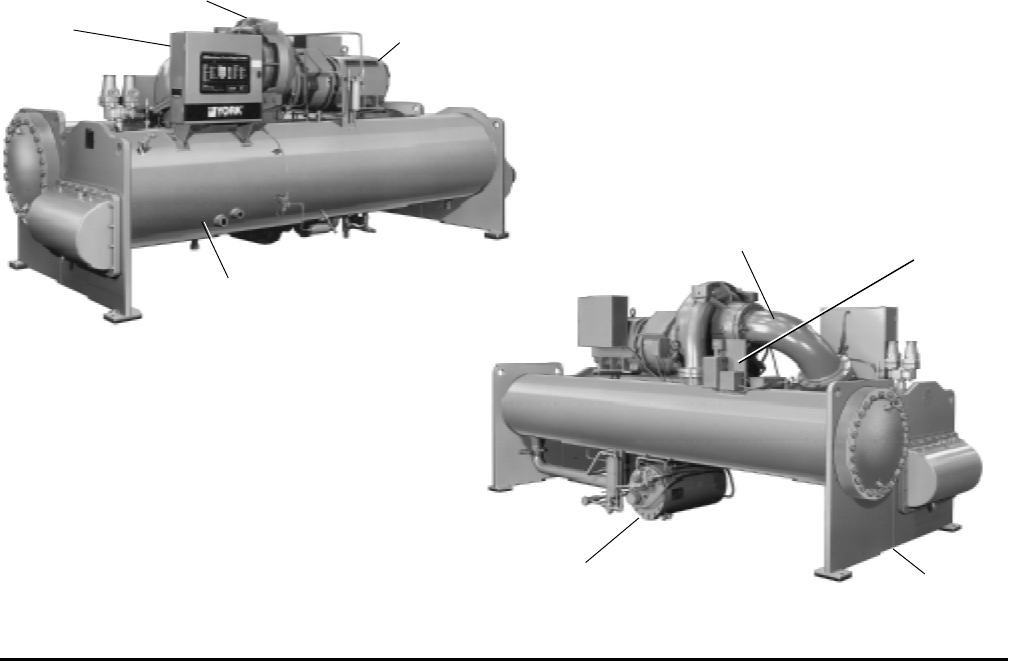
FIG. 1 – MODEL YK MILLENNIUM CHILLER
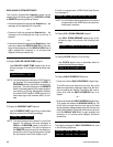
SYSTEM OPERATION DESCRIPTION (See Fig. 2)
The YORK Model YK Millennium Chiller is commonly
applied to large air conditioning systems, but may be
used on other applications. The chiller consists of an
open motor mounted to a compressor (with integral
speed increasing gears) condenser, cooler and flow
control chamber.
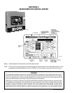
The chiller is controlled by a modern state of the art
MicroComputer Control Center which monitors its op-
eration. The Control Center is programmed by the op-
erator to suit job specifications. Automatic timed start-
ups and shutdowns are also programmed to suit
nighttime, weekends, and holidays. The operating sta-
tus, temperatures, pressures, and other information per-
tinent to operation of the chiller are automatically dis-
played and read on a 40 character alphanumeric
message display. Other displays can be observed by
pressing the keys as labeled on the Control Center.
The chiller with the MicroComputer Control Center is
applied with an electro-mechanical starter, YORK Solid
State Starter (optional), or Variable Speed Drive (op-
tional).
In operation, a liquid (water or brine to be chilled) flows
through the cooler, where boiling refrigerant absorbs
heat from the water. The chilled liquid is then piped to
fan coil units or other air conditioning terminal units,
where it flows through finned coils, absorbing heat from
the air. The warmed liquid is then returned to the chiller
to complete the chilled liquid circuit.
The refrigerant vapor, which is produced by the boiling
action in the cooler, flows to the compressor where the
rotating impeller increases its pressure and tempera-
ture and discharges it into the condenser. Water flowing
through the condenser tubes absorbs heat from the re-
frigerant vapor, causing it to condense. The condenser
water is supplied to the chiller from an external source,
usually a cooling tower. The condensed refrigerant drains
from the condenser into the flow control chamber, where
the flow restrictor meters the flow of liquid refrigerant
to the cooler to complete the refrigerant circuit.
The major components of a chiller are selected to handle
the refrigerant which would be evaporated at full load
CONTROL
CENTER
COMPRESSOR
MOTOR
COOLER
27382A
DISCHARGE LINE
PRE-ROTATION
VANE
ACTUATOR
CONDENSER
OIL RESERVOIR/
PUMP
27385A