


46 YORK INTERNATIONAL
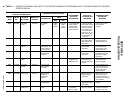
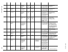
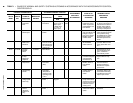
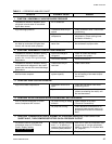
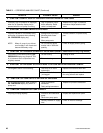
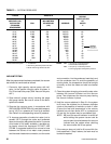
TABLE 1 – CAUSES OF NORMAL AND SAFETY SYSTEM SHUTDOWNS IN ACCORDANCE WITH THE MICROCOMPUTER CONTROL,
CENTER DISPLAY
SHUTDOWN CAUSE
GOVERNING CONTROL FUNCTION
CONTROL CENTER DISPLAY
OPERATING
PROGRAMMED START-UP OF PROBABLE CAUSE
DAY OF TIME OF CAUSE OF METHOD OF
DESCRIPTION
POINT
SETPOINTS SYSTEM AFTER AND SERVICE
WEEK DAY SHUTDOWN RESTART ON ON
BY OPERATOR SHUTDOWN REQUIRED
RISE FALL
MON. 10:00 AM Oil Pressure High Oil Press. 100 PSID (Dur- 59 Will start at 59 This Shutdown is provided
Transducer Transducer ing first 7 min. of PSID PSID when compr. to check on Oil Pressure
Error Compr. Oper.) switch is placed to Transducers for failure in
60 PSID (After STOP/RESET and the high state. Replace
first 7 min. of then START Oil Press. Transducer in
Compr. Oper.) oil sump or compressor
Vane Motor Autostart Vane Motor Restart automatically Vanes are set improperly,
Switch Open Switch after Vane Motor arm reset vane linkage check
linkage is set pro- vane positions using
perly. Press STOP/ the SERVICE key switch
RESET and then and proper keys on the
START switch MicroComputer Control
Center
MON. 10:00 AM Starter Motor Current > Press compressor Check motor starter
Malfunction 15% for 10 swc. STOP/RESET operation. Motor current
Detected with Control Cen- switch and then value greater than 15%
ter not calling for FLA
motor to run
MON. 10:00 AM Program Autostart Micro Board Watchdog timer circuit
Initiated has reset software pro-
Reset gram – Chiller will
automatically restart.
Replace RTC RTC-IC chip Reprogram the Con- Weak battery
IC chip trol Center Setponts Replace RTC-IC chip
Reprogram & proceed with U16
Setpoints Normal Start-up
MON. 10:00 AM Low Oil Autostart Oil Temp. 71.0°F 55°F Press STOP/ Oil Temp. Thermistor
Temperature Thermistor RESET switch & disconnected from
(RT3) then START Analog Input Board.
switch Reconnect or replace
open sensor.
MON. 10:00 AM Faulty Dis- Discharge Temp. 30.0°F 29.9°F Press STOP/ Faulty Discharge Temp.
charge Temp. Thermistor START switch & Thermistor (RT2) or dis-
Sensor (RT2) discon- then START connected from Analog
nected or faulty switch Input Board. Connect or
operating temp. replace open sensor.
= 32°F
MON. 100.00 AM Low Line SSS Logic See legend on wiring Chiller will automa- Low AC Line Voltage
Voltage (SSS Board diagram tically restart when
Units only) all phases of line vol-
tage increase to the
minimum required
starting level.
MON. 10:00 AM MTR Phase SSS Logic See “Section 2” Press STOP/START Motor Phase Current
Current Board switch then START Unbalance
unbalance switch
(SSS Units
only)