


38 YORK INTERNATIONAL
GENERAL
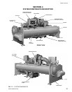
The YORK Model YK Millennium Centrifugal Liquid
Chiller is completely factory-packaged including cooler,
condenser, compressor, motor, lubrication system,
MicroComputer Control Center, and all interconnect-
ing unit piping and wiring.
The initial charge of refrigerant and oil is supplied for
each unit. Oil is shipped in containers with the chiller.
Refrigerant is shipped to the jobsite in cylinders at the
time of installation.
The services of a YORK factory-trained, field service
representative are included to supervise the final leak
testing, charging and the initial start-up and concur-
rent operator instructions.
COMPRESSOR
The compressor is a single-stage centrifugal type pow-
ered by an open-drive electric motor.
The rotor assembly consists of a heat-treated alloy
steel drive shaft and impeller shaft with a cast alumi-
num, fully shrouded impeller. The impeller is designed
for balanced thrust and is dynamically balanced and
over-speed tested.
The inserted type journal and thrust bearings are fabri-
cated of aluminum alloy. Single helical gears with
crowned teeth are designed so that more than one tooth
is in contact at all times. Gears are integrally as-
sembled in the compressor rotor support and are film
lubricated. Each gear is individually mounted in its own
journal and thrust bearings.
The open-drive compressor shaft seal consists of a
spring-loaded, precision carbon ring, high temperature
elastomer “O” ring static seal, and stress-relieved, pre-
cision lapped collars. The seal is oil-flooded at all times
and is pressure-lubricated during operation.
CAPACITY CONTROL
Prerotation vanes (PRV) modulate chiller capacity from
100% to as low as 15% of design for normal air condi-
tioning applications. Operation is by an external, elec-
tric PRV actuator which automatically controls the vane
position to maintain a constant leaving chilled liquid
temperature.
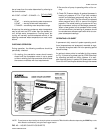
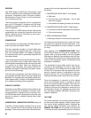
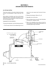
COMPRESSOR LUBRICATION SYSTEM
(See Fig. 18)
The chiller lubrication system consists of the oil pump,
oil filter, oil cooler and all interconnecting oil piping and
passages. There are main points within the motor-com-
pressor which must be supplied with forced lubrication
as follows:
1. COMPRESSOR DRIVE SHAFT (Low Speed)
a. Shaft seal.
b. Front and rear journal bearings – one on each
side of driving gear.
c. Low speed thrust bearing (forward and reverse).
2. COMPRESSOR DRIVEN SHAFT (High Speed)
a. Forward and reverse high speed thrust bearing.
b. Two journal bearings.
3. SPEED INCREASING GEARS
a. Meshing surfaces of drive and pinion gear teeth.
To provide the required amount of oil under the neces-
sary pressure to properly lubricate these parts, a mo-
tor driven submersible oil pump is located in a remote
oil sump.
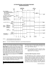
Upon pressing of the COMPRESSOR START switch
on the Control Center, the oil pump is immediately en-
ergized. After a 50 second delay to allow the system
oil pressure to stabilize, the compressor motor will start.
The oil pump will continue to run during the entire op-
eration of the compressor, and for 150 seconds during
compressor coastdown.
The submerged oil pump takes suction from the sur-
rounding oil and discharges it to the oil cooler where
heat is rejected. The oil flows from the oil cooler to the
oil filter. The oil leaves the filter and flows to the emer-
gency oil reservoir where it is distributed to the com-
pressor bearings. The oil lubricates the compressor
rotating components and is returned to the oil sump.
Since the emergency oil reservoir is at the highest
point in the lubrication system, it provides an oil sup-
ply to the various bearings and gears in the event of a
system shutdown due to power failure. The reservoir,
located on the top of the compressor, allows the oil to
be distributed through the passages by gravity flow,
thus providing necessary lubrication during the com-
pressor coastdown.
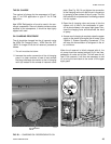
OIL PUMP
For normal operation, the oil pump should operate at
all times during chiller operation. Manual pump opera-
tion may be used to establish stable oil pressure be-
fore starting. When depressed and released, the
MANUAL OIL PUMP key will operate the oil pump for
10 minutes and then automatically shut off. To stop the