


571209-YTG-C-1012
2 Johnson Controls Unitary Products
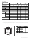
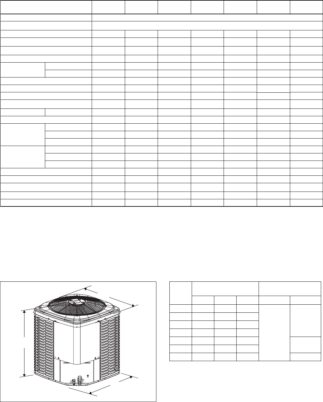
* Adapter fitting required for 1-1/8" line set.
All dimensions are in inches and are subject to change without notice.
Overall height is from bottom of base pan to top of fan guard.
Overall length and width include screw heads.
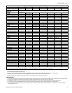
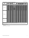
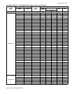
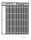
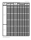
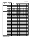
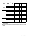
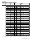
Physical and Electrical Data
MODEL
YHJD18
S41S2
YHJD24
S41S4
YHJD30
S41S4
YHJD36
S41S4
YHJD42
S41S4
YHJD48
S41S4
YHJD60
S41S5
Unit Supply Voltage 208-230V, 1 60Hz
Normal Voltage Range
1
187 to 252
Minimum Circuit Ampacity
11.9 11.2 14.1 19.7 20.9 25.6 42.6
Max. Overcurrent Device Amps
2
20 15 20 30 35 45 70
Min. Overcurrent Device Amps
3
15 15 15 20 25 30 45
Compressor Type
Scroll Recip Recip Recip Recip Recip Scroll
Compressor Amps
Rated Load
9.0 8.3 10.6 14.7 15.7 19.4 33.0
Locked Rotor
48.0 43.0 54.0 74.0 88.0 88.0 134.0
Crankcase Heater
No Yes Yes Yes Yes Yes No
Factory External Discharge Muffler
Yes No No No No No Yes
Factory External Check Valve
No No No No No No No
HS Kit Required with TXV
4
No Yes Yes Yes Yes Yes* No
Fan Motor Amps Rated Load
0.70 0.80 0.80 1.3 1.3 1.3 1.5
Fan Diameter Inches
24 24 24 24 24 24 24
Fan Motor
Rated HP
1/10 1/8 1/8 1/4 1/4 1/4 1/4
Nominal RPM
825 1075 1075 850 850 850 850
Nominal CFM
2000 2900 3000 3800 3800 3600 3550
Coil
Face Area Sq. Ft.
15.7 18.3 21.0 23.6 23.6 23.6 23.6
Rows Deep
1 1 1 1 1 2 2
Fins / Inch
22 22 22 22 22 18 18
Liquid Line Set OD (Field Installed)
3/8 3/8 3/8 3/8 3/8 3/8 3/8
Vapor Line Set OD (Field Installed)
3/4 3/4 3/4 3/4 7/8 7/8 1-1/8
Unit Charge (Lbs. - Oz.)
5
6 - 6 9 - 6 9 - 0 10 - 0 9 - 10 14 - 12 15 - 0
Charge Per Foot, Oz.
0.62 0.62 0.62 0.62 0.67 0.67 .76
Operating Weight Lbs.
172 194 206 218 218 285 290
* These models are shipped with a Hard Start Kit installed at the factory.
1. Rated in accordance with AHRI Standard 110-2012, utilization range “A”.
2. Dual element fuses or HACR circuit breaker. Maximum allowable overcurrent protection.
3. Dual element fuses or HACR circuit breaker. Minimum recommended overcurrent protection.
4. See Hard Start Kit Accessory Installation Manual for Hard Start Kit part number for each model.
5. The Unit Charge is correct for the outdoor unit, smallest matched indoor unit, and 15 feet of refrigerant tubing. For tubing lengths other than 15 feet, add or subtract
the amount of refrigerant, using the difference in length multiplied by the per foot value.
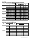
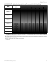
B
C
A
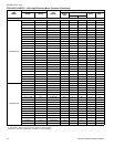
Unit
Model
Dimensions
(Inches)
Refrigerant Connection
Service Valve Size
A B C Liquid Vapor
18 28-1/4 34 34
3/8
3/4
24 32-1/4 34 34
30 36-1/4 34 34
36 40-1/4 34 34
42 40-1/4 34 34
7/8
48 40-1/4 34 34
60 40-1/4 34 34 7/8*