


YORK INTERNATIONAL
67
FORM 150.62-NM1
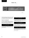
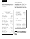
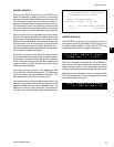
SYS 1 SP = 72.1 PSIG
DP =227.0 PSIG
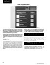
These displays show suction and discharge pressures
for systems 1 & 2. The discharge pressure transducer
is optional on all models
If the
optional
discharge transducer is not installed, the
discharge pressure would display 0 PSIG (0 barg).
Some models come factory wired with a low pressure
switch in place of the suction transducer. In this case,
the suction pressure would only be displayed as the
maximum suction pressure reading of >200 PSIG (13.79
barg) when closed, or < 0 PSIG (0 barg) when open.
The minimum limits for the display are:
Suction Pressure: 0 PSIG (0 barg)
Discharge Pressure: 0 PSIG (0 barg)
The maximum limits for the display are:
Suction Pressure: 200 PSIG (13.79 barg)
Discharge Pressure: 400 PSIG (27.58 barg)
The above two messages will appear sequentially for
each system. The first display shows accumulated run-
ning hours of each compressor for the specific system.
The second message shows the number of starts for
each compressor on each system.
This display of the load and unload timers indicate the
time in seconds until the unit can load or unload.
Whether the systems loads or unloads is determined
by how far the actual liquid temperature is from setpoint.
A detailed description of unit loading and unloading is
covered under the topic of Capacity Control.
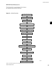
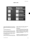
The display of COOLING DEMAND indicates the cur-
rent “step” in the capacity control scheme. The number
of available steps are determined by how many com-
pressors are in the unit. In the above display, the “2”
does not mean that two compressor are running but
only indicates that the capacity control scheme is on
step 2 of 8. Capacity Control is covered in more detail
in this publication which provides specific information
on compressor staging.
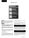
This display indicates the current LEAD system. In this
example system 2 is the LEAD system, making system
1 the LAG compressor. The LEAD system can be manu-
ally selected or automatic. Refer to the programming
under the “Options” key.
A unit utilizing hot gas bypass should
be programmed for MANUAL with
system 1 as the lead system. Failure to
do so will prevent hot gas operation if
system 2 switches to the lead system
when programmed for AUTOMATIC
LEAD/LAG.
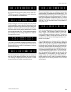
SYS 2 SP = 73.6 PSIG
DP =219.8 PSIG
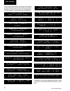
SYS X HOURS 1=XXXXX
2=XXXXX, 3=XXXXX
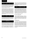
COOL I NG DEMAND
2 OF 8 STEPS
LEAD SYSTEM IS
SYSTEM NUMBER 2
LOAD T IMER = 58 SEC
UNLOAD TIMER = 0 SEC
SYS X STARTS 1=XXXXX
2=XXXXX, 3=XXXXX
2