


YORK INTERNATIONAL
133
FORM 150.62-NM1
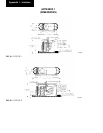
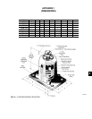
“AEQM” SPRING-FLEX MOUNTING
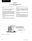
INSTALLATION AND ADJUSTMENT INSTRUCTIONS
APPENDIX 1
1. Isolators are shipped fully assembled and are to be
spaced and located in accordance with installation
drawings or as otherwise recommended.
1a. Locate spring port facing outward from equip-
ment or base so that spring is visible.
2. To facilitate installation, prior to installing, VMC rec-
ommends turning adjusting bolt “B” so that the “Op-
erating Clearance” marked “*” is approximately 1"
to 1-1/2" for 1" deflection units, 1-1/2" to 2" for 1-1/2"
deflection units, and 2" to 2-1/2" for 2" deflection units.
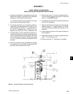
3. Locate isolators on floor or subbase as required, en-
suring that the isolator centerline matches the equip-
ment or equipment base mounting holes. Shim and/
or grout as required to level all isolator base plates
“A”. A 1/4" maximum difference in elevation can be
tolerated.
4. Anchor all isolators to floor or subbase as required.
For installing on concrete VMC recommends HILTI
type HSL heavy duty anchors or equal.
5. Remove cap screw “C” and save. Gently place ma-
chine or machine base on top of bolt “B”. Install cap
screw “C” but DO NOT tighten.
6. The weight of the machine will cause the spring and
thus bolt “B” to descend.
7. Adjust all isolators by turning bolt “B” so that the op-
erating clearance “*” is approximately 1/4". NOTE:
It may be necessary to adjust rebound plate “D” for
clearance.
6. Check equipment level and fine adjust isolators to
level equipment.
9. Adjust rebound plate “D” so that the operating clear-
ance “**” is no more than 1/4".
10.Tighten cap screw “C”. Adjustment is complete.
FIG. 23 – “AEQM” SPRING-FLEX MOUNTING
LD03838
5