


262292-YTG-B-0107
54 Unitary Products Group
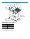
OUTDOOR (CONDENSER) FAN ASSEMBLY
The outdoor fans shall be of the direct-driven propeller type,
discharge air vertically, have aluminum blades riveted to
corrosion resistant steel spider brackets and shall be
dynamically balanced for smooth operation. The 4 outdoor fan
motors shall be totally enclosed with permanently lubricated
bearings, internally protected against overload conditions and
staged independently.
REFRIGERANT COMPONENTS
Compressors:
a. Shall be Scroll compressors internally protected with
internal high-pressure relief and over temperature
protection.
b. Shall have internal spring isolation and sound muffling to
minimize vibration and noise, and be externally isolated
on a dedicated, independent mounting.
Coils:
a. Evaporator and condenser coils shall have aluminum
plate fins mechanically bonded to seamless internally
enhanced copper tubes with all joints brazed. Special
Phenolic coating shall be available as a factory option.
b. Evaporator and Condenser coils shall be of the direct
expansion, draw-thru, design.
Refrigerant Circuit and Refrigerant Safety Components shall
include:
a. Balance-port thermostatic expansion valve with
independent circuit feed system.
b. Filter drier/strainer to eliminate any moisture or foreign
matter.
c. Accessible service gage connections on both suction
and discharge lines to charge, evacuate, and measure
refrigerant pressure during any necessary servicing or
troubleshooting, without losing charge.
d. The refrigeration system shall provide at least 10° F of
sub-cooling at design conditions.
e. All models shall have two independent circuits.
f. Hot gas bypass option shall be factory-installed on
compressor #1 discharge line to provide cooling in low-
load applications. HGBP shall be a standard feature on
VAV models and an optional feature on CV models.
UNIT CONTROLS
a. Unit shall be complete with self-contained low-voltage
control circuit protected by a resetable circuit breaker on
the 24-volt transformer side.
b. Unit shall incorporate a lockout circuit which provides
reset capability at the space thermostat or base unit,
should any of the following standard safety devices trip
and shut off compressor.
c. Loss-of-charge/Low-pressure switch.
1. High-pressure switch.
2. Freeze-protection thermostat, evaporator coil. If any of
the above safety devices trip, a LED (light-emitting
diode) indicator shall flash a diagnostic code that
indicates which safety switch has tripped.
d. Unit shall incorporate "AUTO RESET" compressor over
temperature, over current protection.
e. Unit shall operate with conventional thermostat designs
and have a low voltage terminal strip for easy hook-up.
f. Unit control board shall have on-board diagnostics and
fault code display.
g. Standard controls shall include anti-short cycle and low
voltage protection, and permit cooling operation down to
0 °F.
h. Control board shall monitor each refrigerant safety switch
independently.
i. Control board shall retain last 5 fault codes in non volatile
memory, which will not be lost in the event of a power
loss.
GAS HEATING SECTION (WR***N MODELS)
Shall be designed with induced draft combustion with post
purge logic and energy saving direct spark ignition, redundant
main gas valve. Ventor wheel shall be constructed of stainless
steel for corrosion resistance. The heat exchanger shall be of
the tubular type, constructed of T1-40 aluminized steel for
corrosion resistance and allowing minimum mixed air entering
temperature of 25° F. Burners shall be of the in-shot type,
constructed of aluminum coated steel and contain air mixture
adjustments. All gas piping shall enter the unit cabinet at a
single location through either the side or curb, without any field
modifications. An integrated control board shall provide timed
control of evaporator fan functioning and burner ignition.
Heating section shall be provided with the following minimum
protection:
a. Primary and auxiliary high-temperature limit switches.
b. Induced draft motor speed sensor.
c. Flame roll out switch (automatic reset).
d. Flame proving controls. Unit shall have two independent
stages of capacity.
ELECTRIC HEATING (WR***C/E MODELS)
Nickel chromium electric heating elements shall be provided as
required by the application with 1 or 2 stage control, as
required, from 13.5 KW to 72 KW capacities. The heating
section shall have a primary limit control(s) and automatic reset
to prevent the heating element system from operating at an
excessive temperature. Units with Electric Heating shall be
wired for a single point power supply with branch circuit fusing
(where required).