


262292-YTG-B-0107
Unitary Products Group 5
• Electric Heat Operation - All electric heat models
(factory installed only) are wired for a single power source
and include a bank of nickel chromium elements mounted
at the discharge of the supply air blower to provide a high
velocity and uniform distribution of air across the heating
elements. Every element is fully protected against
excessive current and temperature by fuses and two
thermal limit switches.
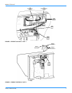
• The power supply wiring can be routed into the control
box through a threaded pipe connection in the base pan of
the unit or through a knockout in the wiring panel on the
front of the unit.
• BAS Controls - York’s Magnum series units offer factory
mounted BAS controls such as Novar, Honeywell,
Johnson, and CPC.
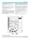
REHEAT MODE SEQUENCE OF OPERATION
The reheat control board allows the user to select two different
modes of operation via a jumper connection on the board. (See
Figure 2.) Each mode is described below. Refer to Figures 2 - 4
when reading this section.
“NORMAL” MODE
When the reheat control board (RCB) detects a need for
dehumidification (24VAC) at "HUM" via the field supplied
dehumidistat connected to RHTB-1 and RHTB-2 and there is
not a call for cooling, it energizes the hot gas relay (HGR),
which energizes the 3-way valve (SOL 3), the condenser coil
valve (SOL 2), and de-energizes the reheat coil bleed valve
(SOL 1). The Y1 signal is passed to the unit control board
(UCB), which engages circuit # 1, resulting in circuit #1 reheat
mode operation.
When the room thermostat calls for first stage cooling, with or
without a call for dehumidification, the RCB senses a signal
through "Y1", de-energizing the HGR, which de-energizes SOL
3 and SOL 2, and energizes SOL 1, engaging circuit # 1,
resulting in circuit #1 cooling mode operation.
When the room thermostat calls for second stage cooling, the
RCB senses a signal through "Y1" & "Y2" and engages circuit
#1 and circuit #2 in the cooling mode.
Indoor blower operation is initiated upon a call for first stage
cooling, second stage cooling or dehumidification.
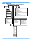
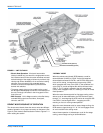
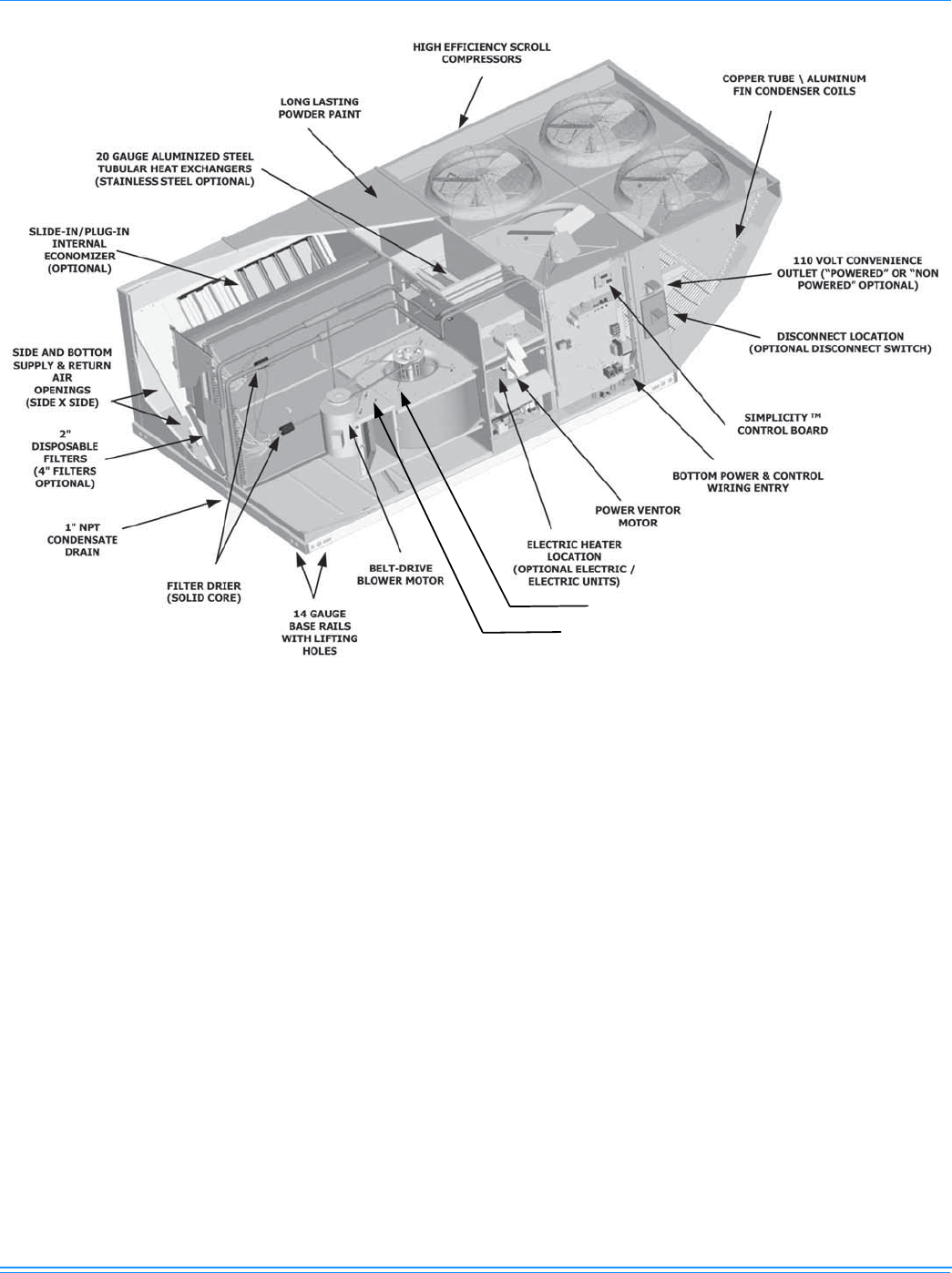
FIGURE 1: UNIT CUTAWAY
LOCATION OF VFD (Optional)
LOCATION OF VFD BYPASS (Optional)