


262292-YTG-B-0107
46 Unitary Products Group
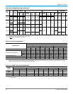
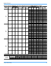
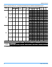
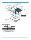
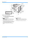
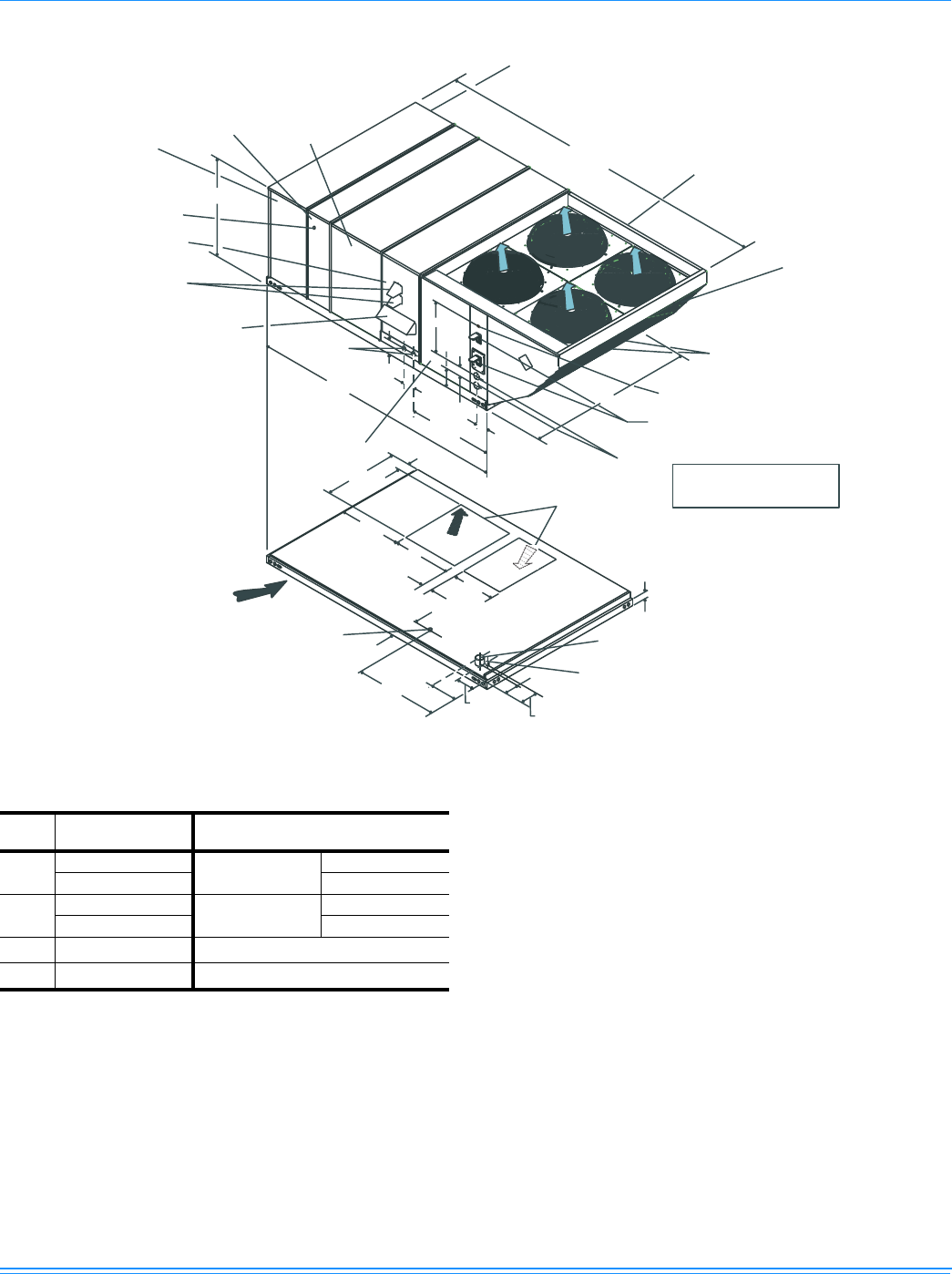
FIGURE 12:UNIT DIMENSIONS WR180, 240 & 300 (FRONT VIEW)
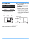
TABLE 34: UTILITIES ENTRY DATA
HOLE
OPENING SIZE
(DIA.)
USED FOR
A
1-1/8” KO
Control Wiring
Side
3/4” NPS (Fem.) Bottom
B
3-5/8” KO
Power Wiring
Side
3” NPS (Fem.) Bottom
C
2-3/8” KO
Gas Piping (Front)
1
1. One-inch gas piping NPT required.
D
1-11/16” Hole
Gas Piping (Bottom)
1
,
2
2. Opening in the bottom of the unit can be located by the slice in
the insulation.
NOTE:
All entry holes should be field sealed to prevent rain
water entry into the building.
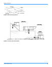
11-1/2
(A) CONTROL WIRING
ENTRY
COIL
GUARD
KIT
CONDENSER
COILS
All dimensions are in inches. They are
subject to change without notice.
Certified dimensions will be provided
upon request.
(B) POWER
WIRING
ENTRY
5
9-3/4
21.00
6-3/8
7-1/8
35
5-7/8
136-1/4
GAS OR ELECTRIC
HEAT
ACCESS
DOT PLUG
(For pressure
drop reading)
BLOWER
COMPARTMENT
ACCESS
(C) GAS
SUPPLY
ENTRY
CONTROL BOX
ACCESS
VENT AIR
OUTLET
HOODS
BLOWER MOTOR
ACCESS (Location of
Optional VFD Bypass)
BLOWER ACCESS
(Location of
Optional VFD)
52-5/8
180-19/32
COMPRESSOR ACCESS
DISCONNECT
SWITCH
LOCATION
ECONOMIZER / MOTORIZED DAMPER
FIXED OUTDOOR INTAKE AIR AND
POWER EXHAUST RAIN HOODS
(See detail Y)
92
46-5/8
35-1/4
33
2-3/4
3-3/4
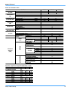
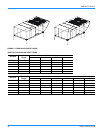
(B) POWER WIRING
ENTRY
BOTTOM SUPPLY
AND RETURN
AIR OPENINGS
(See Note)
(A) CONTROL WIRING
ENTRY
21-1/2
11-1/8
(D)
GAS SUPPLY
ENTRY
UNIT BASE RAILS
Shown separately to illustrate
RETURN
AIR
Bottom Duct openings. Power
and Gas Piping Connection
location.
NOTE:
For curb mounted units, refer to the curb hanger
dimensions of the curb for proper size of the
supply and return air duct connections.
12-1/2
9-1/4
8-1/8
46-5/8
9-3/4
COMBUSTION
AIR INLET HOOD
SUPPLY
AIR