


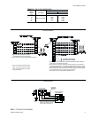


heater accessory installation instruction for the heater
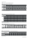
electrical data.
The minimum air flow limitations across these heaters are
listed in Table 2.
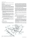
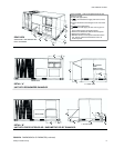
OPTIONAL ECONOMIZER RAIN HOOD
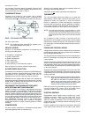
The following procedure should be used when assembling an
economizer rain hood onto a unit. Refer to Figure 4. The
outdoor and return air dampers, damper actuator, the linkage
and all the controls are factory mounted as part of the
economizer option.
All of the hood components, including the filters, the gasketing
and the hardware for assembling are located above the top
filter racks within the filter section. The outdoor air sensor is in
thebagofpartslocatedatthe bottomofthereturn airsection.
1. With filter section access panel removed, take out hood
components, filters and sensor described above. Remove
and discard outdoor air opening cover on back unit (Upper
right hand corner).
2. Remove the 13mm (
in.) knockout (A) in the units rear
panel (located to the right side of the outdoor air opening).
Insert the two loose wires from inside the unit, into the
13mm (
in.) bushing provided. Insert wires and bushing
into knockout. Snap bushing into place.
3. Mount the outdoor air sensor to the rear panel, just below
the knockout described in Step 2. Secure with two self-
drilling screws at dimples (B) provided in the panel.
NOTE: Sensor must be positioned so that the sensing ports
are at the top (louvers pointing downward) and termi-
nal connections to the right.
4. Connect the two wires, indicated in Step 2, to the sensor as
follows:
•
Wire #73 to terminal (+)
•
Wire #74 to terminal (S)
5. Assemble the LH and RH side plates to the top cover (2
screws each side) to form the hood. Apply gasketing to the
flange surface on each side plate. Extend gasketing 6mm (
in.) beyond top and bottom of each flange to insure ade
-
quate cornersealing. Secure thisassembly to the unitback
panel(upper right hand corner). First, remove screw (C) on
unit top cover. Then slip flange of hood cover in under
flange of unit top cover, replace screw (C), engaging hole
(E) in hood flange and tighten. Attach the two side plates to
the unitpanel byusing two self-drillingscrews for each side
plate at dimples (D) provided in the panel.
6. Position fillpiece at bottom of hood, between the two side
plates but do not secure at this time. (Slotted openings
MUSTbedownward fordrainage). Afterfillpiece isproperly
positioned, note where contact is made with the unit panel.
Remove fillpiece and apply gasket material to this area to
provide a seal. Reposition fillpiece and secure with 2
screws.
7. Install the two filters into the hood assembly, sliding down
along retainers on side plates, into fillpiece at bottom of
hood.
NOTE: Install filters so that “Air Flow” arrows point toward the
unit.
8. Install filter cover over the end of the hood with one screw
(center of hood), securing filters into position.
CAUTION: When proceeding with steps 9 and 10, extreme
care must be exercised while turning both the set
point and minimum position adjusting screws to
prevent twisting them off.
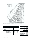
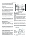
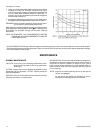
9. The enthalpy set point for the dampers may now be set by
selectingthe desired set-point fromgraph in Figure5. For a
single enthalpy economizer, carefully turn the set-point ad-
justing screw to the “A”, “B”, “C” or “D” setting correspond-
ing to the lettered curve. For a dual enthalpy economizer,
carefully turn the set-point adjusting screw fully clockwise
past the “D” setting.
10. To check that the damper blades move smoothly without
binding, carefully turn the minimum position adjusting
035-12984-001-A-0204
6 Unitary Products Group
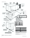
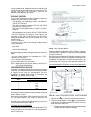
FIG. 4 - ECONOMIZER RAIN HOOD ASSEMBLY (OPTION)
B
GASKET
C
HOOD
COVER
OUTDOOR AIR
SENSOR
A
FILTER SECTION
ACCESS PANEL
D
GASKETED
FLANGE
R. H.
SIDE
PLATE
D
E
D
D
GASKETED
FLANGE
FILTER
COVER
L. H. SIDE
PLATE
FILTERS
FILLPIECE
OUTDOOR AIR
OPENING COVER
SIDE DUCT
APPLICATION SHOWN