


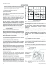


During troubleshooting, the defrost time can be reduced to 20
seconds by shorting out the SW1 test pegs on the module. The
pegs are 13mm (
in.) long, 1mm ( in.) apart and are
mounted on a white base. See Figure 8.
LOCKOUT CONTROL
Any one of four conditions will put the system into a lock-out
condition during the heating or cooling mode:
1.
The discharge line temperature reaches 124°C (255°F)
(102°C [215°F] reset) or,
2. The discharge pressure reaches 2770 kPa (398 PSIG)
(2158 kPa [310 PSIG] reset) or,
3.
The suction line freezestat equals -3°C (26°F) (3°C [38°F]
reset) or,
4. The low-pressure cut-out equals 49 kPa (7 PSIG) (153 kPa
[22 PSIG] reset).
A lock-outl energizes the emergency heat light on the
thermostat and the red LED light on the unit relay board.
Turning the thermostat switch to “Off” then back to “On”, will
reset the system.
NOTICE TO OWNER:
If a lockout occurs, check for the following problems before
calling a serviceman:
1. Dirty filters.
2. Snow accumulation.
3. Leaf or debris blockage.
After eliminating the problem, attempt to restart the system as
follows:
•
turn the system switch on the thermostat to its “OFF”
position for 10 seconds.
•
turn it back to its original position.
If the unit doesn't start, call a serviceman.
NOTE: Models with an anti-recycle accessory will have a 5-
minute delay before starting.
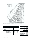
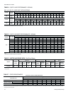
CHECKING SUPPLY AIRFLOW
The speed of the supply air blower will depend on the required
airflow, the unit accessories and the static resistances of both
the supply and the return air duct systems. With this
information, the speed for the supply air blower can be
determined from the blower performance and static resistance
data on Tables 4, 5 and 7.
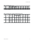
Knowing the required blower RPM and the blower motor kW
(HP), the speed setting for the supply air motor can be
determined.
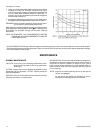
The setting (turns open) for the optional belt-drive supply air
pulley can be determined from Table 10.
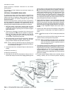
OPTIONAL BELT-DRIVE BLOWER
All unitswith belt-drive blowers have single speed motors.The
variable pitch pulley on the blower motor can be adjusted to
obtain the desired supply airflow. Refer to Table 6 for blower
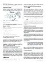
motor drive data. The tension on the belts should be adjusted
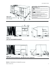
as shown in Figure 9.
Startthe supplyair blower motor.Adjust theresistances inboth
the supply and the return air duct systems to balance the air
distribution throughout the conditioned space. The job
specifications may require that this balancing be done by
someone other than the equipment installer.
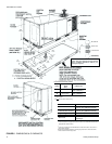
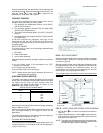
To check the supply airflow after the initial balancing has been
completed:
1. Drill two 8mm ( in.) holes in the side panels as shown in
Figure 10.
2. Insert at least 203mm (8 in.) of 6mm (
in.) tubing into each
of these holes for sufficient penetration into the air flow on
both sides of the indoor coil.
NOTE: The tubes must be inserted and held in a position per
-
pendiculartothe airflowsothat velocitypressuredoes
not affect the static pressure readings.
035-12984-001-A-0204
Unitary Products Group 13
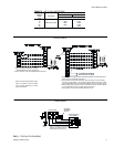
TURNS
OPEN*
BLOWER DRIVE RANGE (RPM)
060
5
4
3
2
1
0
850
916
982
1048
1114
1180
*Pulley can be adjusted in half-turn increments.
TABLE 10 - BELT-DRIVE SUPPLY AIR
MOTOR PULLEY ADJUSTMENT
FIG. 9 - BELT ADJUSTMENT
FIG. 10 - HOLE LOCATIONS (PRESS. DROP READING)
419
“
435
“
533
21"
“ HOLES
DUCT FLANGES
(Back of Unit)
DAMPER
ASSEMBLY
FILTERS
INDOOR
COIL
FRONT OF UNIT
L.H. END VIEW
(Filter Access End)