


screw fully clockwise and then energize and de-energize
terminals “R” to “G”. With terminals “R” to “G” energized,
turn the minimum position screw counterclockwise until the
desired minimum position has been attained.
11. Replace the filter section access panel.
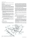
COOLING SYSTEM
The unit has an air-cooled condenser and is factory-charged
with Refrigerant-22.
The compressor is hermetically sealed, internally sprung,
mounted on spring isolators and inherently (internally)
protected. If there is an abnormal temperature rise in the
compressor,theprotectoropensto shutdownthecompressor.
PRELIMINARY OPERATION COOLING
After the installation has been completed, the crankcase
heaterof thecompressormust beenergized foratleast 4hours
before starting the unit. After this initial warm-up, the
compressor should be given three false starts (energized just
long enough to make a few revolutions) with a 5 minute delay
between each start before being put into full time service.
NOTE: Prior to each cooling season, the crankcase heater
must be energized at least 10 hours before the system
is put into operation.
COOLING SEQUENCE OF OPERATION
When the thermostat calls for cooling, the compressor and the
outdoor fan motor will be energized through terminal “Y1" and
the supply air blower motor will be energized through terminal
”G" (if the fan switch on the subbase is set in the “AUTO”
position). The supply air blower motor will run continuously if
the fan switch is set in the “ON” position.
The reversing valve is energized thru the “O” circuit when the
subbase is in the cooling mode.
HEATING SEQUENCE OF OPERATION
The following sequence of operation is based on using a
standardYORKheatpumpthermostatwithtwo heatingstages.
FIRST STAGE HEAT
When the thermostat calls for heating, the compressor and the
outdoor fan motor will be energized through terminal “Y1" and
the supply air blower motor will be energized through terminal
”G" (if the fan switch on the subbase is set in the “AUTO”
position). The supply air blower motor will run continuously if
the fan switch is set in the “ON” position.
SECOND STAGE HEAT
If compressor operation can not satisfy the heating
requirements, second stage heat will energize supplemental
electric heat (if supplied) thru the “W1" circuit.
DEFROST SEQUENCE OF OPERATION
The BCH has a unique “ambient modified” time-temperature
defrost control that automatically adjusts to changes in the
outdoor temperature. The defrost control will shorten the
defrost initiation time periods above 2°C (35°F) and will extend
the defrostinitiation time periodsbelow 2°C (35°F).The control
is factory set to defrost at 110 minutes (T3), but it can be field
adjusted to defrost at 80 minutes (T2) or 50 minutes (T1) in
areas with high humidity.
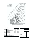
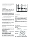
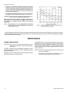
The curve in Figure 7 shows how defrost initiation times are
automatically compensated for changes in outdoor
temperature.
EXAMPLE: If the time is factory set on pin T-3 (110 minutes at
2°C(35°F) outdoor)andthe outdoortemperature climbsto 7°C
(45°F), the time initiation cycle decreases to 100 minutes.
If the outdoor temperature drops to -12°C (10°F) where ice is
less likely to form, the 110 minute interval increases to 150
minutes.
Two requirements must be met before a defrost cycle can be
initiated.
1. The defrost time cycle must be complete.
2. The liquid line temperature must be less than -2°C (28°F).
Defrost terminates when the liquid line sensor reaches 13°C
(55°F) or after 10 minutes.
The defrost time cycle restarts 10 minutes after the start of the
defrost cycle even though the liquid sensor terminated defrost
after 3 minutes.
035-12984-001-A-0204
12 Unitary Products Group
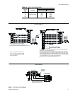
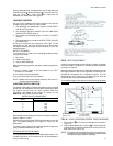
FIG. 7 - DEFROST INITIATION TIMES
FIG. 8 - AMBIENT MODIFIED TIME/TEMPERATURE
CONTROL
T1 - 50 Minute Setting
T3 - 110 Minute Setting (Factory Set Point)
T2 - 80 Minute Setting
200
-10
0
10
20
30
40
50
250
150
100
50
0
60
OUTDOOR AMBIENT, DEG. F
TIME BETWEEN DEFROST CYCLES, MINUTES
OPERATION
T1 - 50 MINUTE SETTING
T2 - 80 MINUTE SETTING
T3 - 110 MINUTE SETTING
(Factory Set Point)
SHORTING PEGS TO
OVERRIDE TIMER
FOR SERVICE
MOVABLE JUMPER
WIRE TO CHANGE
DEFROST TIMER