


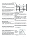

LIMITATIONS
These units must be installed in accordance with national and
local or municiple safety codes: Refer to Table 1 for Unit
Application Data.
If components are to be added to a unit to meet local codes, they
aretobeinstalledat thedealer'sand/or thecustomer'sexpense.
LOCATION
Use the following guidelines to select a suitable location for
these units.
1. Unit is designed for outdoor installation only.
2. Outdoor coil must have an unlimited supply of air.
3. For ground level installation, use a level concrete slab with
a minimum thickness of 102mm (4 in.). The length and
width should be at least 152mm (6 in.) greater than the unit
base rails. Do not tie slab to the building foundation.
4. Roofstructures must be able to support the weight of the unit
and its options and / or accessories. Unit must be installed on
a solid level roof curb or appropriate angle iron frame.
CAUTION: If a unit is to be installed on a roof curb or special frame
other than a YORK roof curb, gasketing must be applied
toallsurfacesthat comeincontactwiththeunitunderside.
5. Maintain level tolerance to 13mm (
in.) maximum across
the entire length or width of the unit.
6. Elevate the unit sufficiently to prevent any blockage of the
airentrances by snow inareas where therewill be snowac
-
cumulation. Check the local weather bureau for the ex
-
pected snow accumulation in your area.
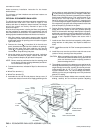
OUTDOOR COIL CONDENSATE DRAINAGE PRECAUTION
Condensatedrainsfrom theoutdoorcoilduring theheatingand
defrost cycles. Normally this condensate may be allowed to
drain directly onto the ground/roof. A gravel bed is
recommended to prevent mud splashing.
WARNING:Theunit should not be installed in an area where mud
or ice could cause personal injury. Remember that
condensate drips from the outdoor coil during heat
and defrost cycles and that this condensate freezes
when the temperature of the outdoor air is below 0°C
(32
F).
RIGGING AND HANDLING
Exercise care when moving the unit. Do not remove any
packaging until the unit is near the place of installation. Rig the
unit by attaching chain or cable slings to the lifting holes
provided in the base rails. Spreaders, whose length exceeds
the largest dimension across the unit, MUST be used across
the top of the unit.
BEFORE LIFTING A UNIT, MAKE SURE THAT ITS WEIGHT
IS DISTRIBUTED EQUALLY ON THE CABLES SO THAT IT
WILL LIFT EVENLY.
Units may also be moved or lifted with a forklift. Slotted
openings in the base rails are provided for this purpose.
LENGTH OF FORKS MUST BE A MINIMUM OF 1067mm
(42 in.).
Remove the nesting brackets from the four corners on top of
the unit. All screws that are removed when taking these
brackets off must be replaced on the unit.
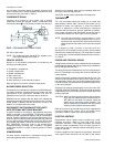
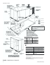
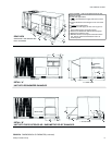
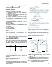
RefertoTable3for unitweightsandtoFigure 1forapproximate
center of gravity.
CLEARANCES
All units require certain clearances for proper operation and
service. Refer to Figure 6 for the clearances required for
combustibleconstruction,servicing,and properunitoperation.
WARNING:Do not permit overhanging structures or shrubs to
obstruct outdoor air discharge outlet.
DUCTWORK
A closed return duct system shall be used. This does not
preclude use of economizers or outdoor fresh air intake. The
supply and return air duct connections at the unit should be
madewithflexiblejointsto minimizethetransmissionofnoise.
The supply and return air duct systems should be designed for
theairflow andstaticrequirementsof thejob. TheyshouldNOT
be sized to match the dimensions of the duct connections on
the unit.
CAUTION: When fastening ductwork to the side duct flanges
on the unit, insert the screws through the duct
flanges only. DO NOT insert the screws through
the casing.
Outdoor ductwork must be insulated and water
-
proofed.
Refer to Figure 6 for information concerning side and bottom
supply and return air duct openings.
FILTERS
Each unit is supplied with 25mm (1 in.) filters . Replacement
51mm (2 in.) filters may be used without modification to the
filter racks. Filters must always be installed ahead of the
evaporator coil and must be kept clean or replaced with same
035-12984-001-A-0204
Unitary Products Group 3
INSTALLATION
FIG. 1 - CENTER OF GRAVITY
2089
“
1035
“
1140
“
502
“
APPROXINATE
CENTER OF
GRAVITY
FRONT
BACK
CONDENSER
COIL END
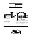
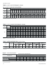
Voltage Variation
Min. / Max.
342 / 457
Cooling
Wet Bulb Temperature of Air
on Indoor Coil, Min./Max.
°C 14 / 22
°F 57 / 72
Dry Bulb Temperature of Air
on Outdoor Coil, Min./Max.
°C 7 / 49
°F 45 / 120
Heating
Minimum Dry Bulb Temperature
of Air on Outdoor Coil
°C -23
°F -10
TABLE 1 - UNIT APPLICATION DATA