


035-12984-001-A-0204
10 Unitary Products Group
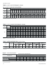
TABLE 4 - SUPPLY AIR PERFORMANCE - BCH048
MODEL
AIR FLOW
m
3
/s / CFM
Available External Static Pressure -Pa/ IWG*
223 / 0.90 248 / 1.00 273 / 1.10 298 / 1.20 322 / 1.30 347 / 1.40 372 / 1.50
RPM Watts RPM Watts RPM Watts RPM Watts RPM Watts RPM Watts RPM Watts
060
1.18 / 2500 --------------
1.13 / 2400 1193 1665 ------------
1.08 / 2300 1170 1580 1202 1620 ----------
1.04 / 2200 1148 1480 1180 1530 ----------
0.99 / 2100 1121 1385 1155 1425 1190 1475 --------
0.94 / 2000 1100 1285 1133 1340 1169 1385 1205 1445 ------
0.90 / 1900 1079 1180 1110 1240 1143 1280 1178 1330 1222 1375 ----
0.85 / 1800 1058 1060 1090 1135 1122 1190 1158 1240 1196 1295 ----
0.80 / 1700 1035 960 1071 1030 1103 1100 1134 1140 1164 1175 1197 1205 - -
0.75 / 1600 1020 900 1056 965 1088 1035 1118 1065 1145 1105 1170 1130 1198 1150
0.71 / 1500 1004 860 1038 880 1070 925 1101 980 1130 1045 1158 1075 1184 1110
*INCLUDES ALLOWANCES FOR AWET INDOOR COILAND 1" FILTERS. REFER TO THE STATIC RESISTANCES TABLE FOR RESISTANCE VALUES ON APPLICATIONS OTHER
THAN
HEAT PUMPUNITS WITH SIDE DUCT AIRFLOWS.
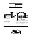
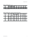
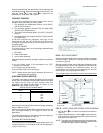
TABLE 5 - SUPPLY BLOWER PERFORMANCE - BCH060
MODEL
BLOWER
RANGE
(RPM)
MOTOR*
ADJUSTABLE
MOTOR PULLEY
FIXED
BLOWER PULLEY
BELT
kW/HP RPM
FRAME
SIZE
SERVICE
FACTOR
PITCH
DIA.
mm (in.)
BORE
mm (in.)
PITCH
DIA.
mm (in.)
BORE
mm (in.)
PITCH
LENGTH
(mm in.)
DESIG-
NATION
BCH060 850 - 1180 0.75/1.0 1450 56 1.15
71 - 97
(2.8 - 3.8)
22 127 (5.0) 25 (1) 947 (37.3) A36
*All motors have solid bases and are inherently protected. These motors can be selected to operate into their service factor because they are located in the moving air, upstream of any
heating device.
TABLE 6 - MOTOR AND DRIVE DATA - Belt-Drive Blower
MODEL
MOTOR
SPEED
Available External Static Pressure - Pa*
m
3
/s Watts m
3
/s Watts m
3
/s Watts m
3
/s Watts m
3
/s Watts m
3
/s Watts m
3
/s Watts m
3
/s Watts m
3
/s Watts
048
HI
MED
LOW
-
0.85
0.77
-
910
810
-
0.84
0.76
-
880
780
0.94
0.82
0.75
1010
850
760
0.92
0.80
0.73
975
825
740
0.90
0.79
0.73
945
800
730
0.87
0.76
0.71
910
775
715
0.83
0.74
0.69
825
740
690
0.78
0.70
0.66
825
700
660
0.72
0.66
0.61
775
660
615
MODEL
MOTOR
SPEED
Available External Static Pressure - IWG*
0.20 0.30 0.40 0.50 0.60 0.70 0.80 0.90 1.00
CFM Watts CFM Watts CFM Watts CFM Watts CFM Watts CFM Watts CFM Watts CFM Watts CFM Watts
048
HI
MED
LOW
-
1810
1635
-
910
810
-
1780
1610
-
880
780
2000
1740
1580
1010
850
760
1950
1700
1555
975
825
740
1905
1665
1540
945
800
730
1840
1620
1510
910
775
715
1770
1560
1460
825
740
690
1660
1480
1400
825
700
660
1530
1390
1300
775
660
615
*INCLUDES ALLOWANCES FOR AWET INDOOR COILAND 1" FILTERS. REFER TO THE STATIC RESISTANCES TABLE FOR RESISTANCE VALUES ON APPLICATIONS OTHER
THAN HEAT PUMPUNITS WITH SIDE DUCT AIRFLOWS.
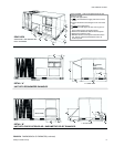
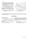
380 / 415 VOLTS - SIDE DUCT APPLICATIONS
EXTERNAL STATIC PRESSURE DROP
DESCRIPTION
RESISTANCE, Pa/IWG
m
3
/s/CFM
0.47/1000 0.57/1200 0.66/1400 0.75/1600 0.85/1800 0.94/2000 1.04/2200 1.13/2400 1.232600
Economizer/Motorized Damper
1, 2
17 / 0.07 20 / 0.08 22 / 0.09 27 / 0.11 32 / 0.13 37 / 0.15 42 / 0.17 50 / 0.20 57 / 0.23
Electric Heaters
1
5 - 15 KW 10 / 0.04 12 / 0.05 15 / 0.06 17 / 0.07 20 / 0.08 25 / 0.10 30 / 0.12 35 / 0.14 40 / 0.16
20 - 30 KW 15 / 0.06 17 / 0.07 20 / 0.08 22 / 0.09 27 / 0.11 32 / 0.13 37 / 0.15 42 / 0.17 50 / 0.20
Bottom Duct Connections
1
15 / 0.06 17 / 0.07 20 / 0.08 22 / 0.09 25 / 0.10 27 / 0.11 30 / 0.12 35 / 0.14 40 / 0.16
1Deduct these resistance values from the available external static pressure shown in the respective Blower Performance Table.
2
The pressure thru the economizer is greater for 100% outdoor air than for 100% return air. If the resistance of the return air duct system is less than 0.25 IWG, the unit will deliver less CFM
during full economizer operation.
TABLE 7 - STATIC RESISTANCES*