


-- With the main burner in operation, check all
connections, hose connections, fittings and
joints as well as the gas control valve inlet and
outlet connections with approved gas leak
detectors.
-- If a leak is detected, check the components
involved for cleanliness in the thread areas
and proper application of pipe compound
before further tightening.
-- Tighten the gas connection as necessary to
stop the leak.
-- If necessary, replace the parts or components
involved if the leak cannot be stopped.
-- Ensure all gas leaks have been identified and
repaired before proceeding.
11. A qualified service agency must check for proper
operating gas pressure upon installation of the
heater.
12. Light according to instructions on heater or within
owner's manual.
13. It is extremely important to use the proper size and
type of gas supply line to assure proper functioning of
the heater. Contact your fuel gas supplier for proper
line sizing and installation.
14. This heater can be configured for use with either L.P.
gas vapor withdrawal or natural gas. Consult the
dataplate for the gas configuration of the specific
heater. Do not use the heater in an L.P. gas liquid
withdrawal system or application. If you are in doubt,
contact the L.B. White Co., Inc.
15. Eventually, like all electrical/mechanical devices, the
thermostat can fail. Thermostat failure may result in
either an underheating or overheating condition which
may damage or kill plants. Plants should be protected
by a separate back-up control system that limits high
and low temperatures and also activates appropriate
alarms.
16. Take time to understand how to operate and maintain
the heater by using this Owner’s Manual. Make sure
you know how to shut off the gas supply to the
building and also to the individual heater. Contact
your fuel gas supplier if you have any questions.
17. Any defects found in performing any of the service or
maintenance procedures must be eliminated and
defective parts replaced immediately. The heater
must be retested by properly qualified service
personnel before placing the heater back into use.
18. Do not exceed input rating stamped on the dataplate
of the heater. Do not exceed the burner manifold
pressure stated on the dataplate. Do not use an
orifice size different than specified for the specific
input rating of this heater, fuel type configuration and
altitude.
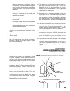
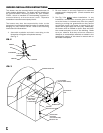
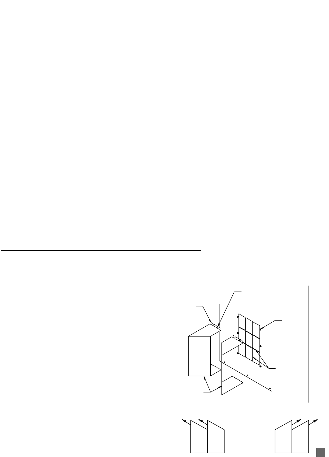
1. Optional air diverters can be installed in the heater
outlet to provide direction to the heated air as it exits
the heater. Installation options include installing the
diverters in such a way as to broadly distribute the air
in two 45 degree paths or to focus the air flow in one
45 degree direction. See Fig. 1.
2. The air diverters may require hand forming prior to
installation. Make 90 degree bends utilizing the
performations provided. Diverter should then have
the shape shown in Fig. 1.
3. The air diverter’s tabs on each half will pop into the
blower outlet between the inside of the case
assembly and the blower housing outlet. If the
notched tabs do not pop into the blower outlet, loosen
(do not remove) the blower outlet screws. Doing this
provides a gap into which you can insert the tabs.
Retighten the screws after installation.
FIG. 1 (Typical installation allowing two directions of air movement.)
(Optional accessory on some models.)
(Appearance of the outlet on heater may vary from model to model.)
AIR DIVERTER
INSTALLATION INSTRUCTIONS
Alternate Air Diverter Installations
TABS
DIVERTER
HALVES
OUTLET
SCREWS
FORMED
OUTLET GUARD
NOTCHES IN MOUNTING TABS
8