


ON
OFF
For initial start-up after heater installation, follow steps 1-6.
For normal start-up, simply set the thermostat above room
temperature.
1. Connect electrical cord to an approved electrical
outlet.
2. Set thermostat to desired room temperature.
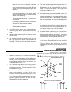
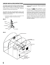
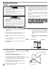
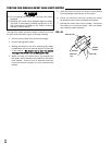
3. This heater has a manually operated toggle style
selector switch located on the top of the control box.
(Open the fan motor access panel to view) This
switch allows you to either heat or ventilate (no heat).
See Fig. 6 for selector switch positions.
FIG. 6
A. HHeating
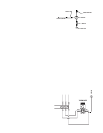
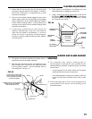
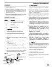
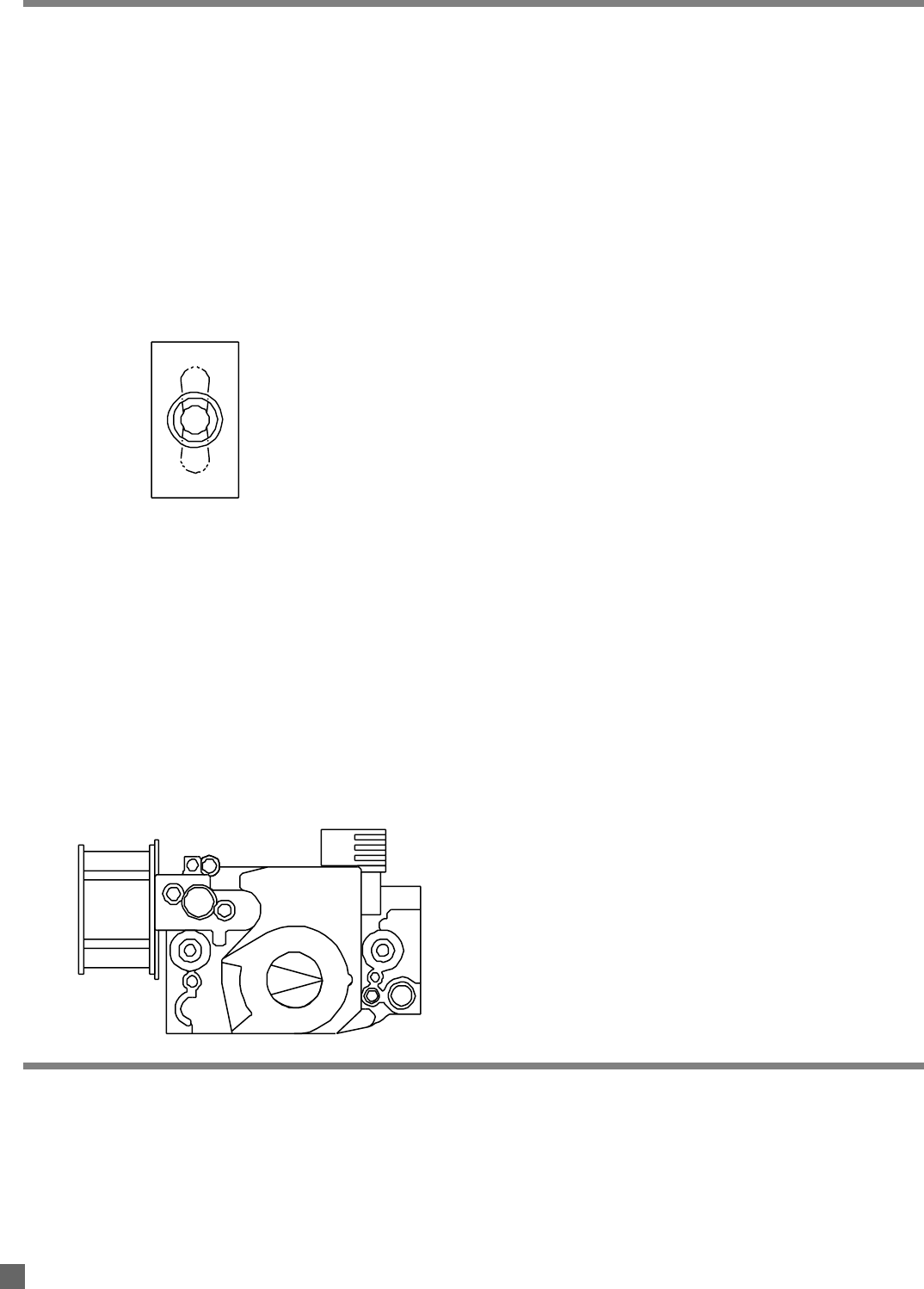
a. Open all manual fuel supply valves. Check for gas
leaks using an approved leak detector. The gas
control valve on the heater has a manual shut-off
feature incorporated into the valve assembly. Make
sure the indicator on the valve is turned to the on
position. See Fig 7.
b. When the selector switch is positioned to heat, the
red light on the ignition control will be on. At this
point, the motor will start, the igniter will spark and
ignition will occur. The heater will cycle based upon
interconnected control system.
FIG. 7
B. VVentilation
When the selector switch is positioned to vent, the
red light will NOT be on. The fan motor will start, but
the igniter will not spark, nor will ignition occur. This
feature is used typically when heat is not needed, but
air circulation is required. To discontinue the
ventilation feature, position the switch to off or heat,
or use the interconnected contacts (customer
supplied) to accomplish this task.
C. OOff
Position the switch to midpoint.
ATTENTION
■ It is normal for air to be trapped in gas hose on new
installations. The heater may attempt more than one
trial for ignition before air is finally purged from line and
ignition takes place.
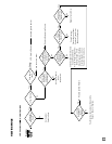
4. The direct spark ignition (DSI) control board within
this heater is self-diagnostic. The board works in
conjunction with a light emitting diode (L.E.D.) built
into the selector switch. The L.E.D. will flash a
specific continuous flash pattern depending on a
problem that occurs. Match the specific flash pattern
given by L.E.D. to the troubleshooting label applied to
inside of burner cap access panel of the heater. The
troubleshooting label identifies the causes of the
problem as it relates to specific flash pattern and
remedies to correct the problem. See also
Troubleshooting Data within this Owner’s Manual.
5. The gas control valve in this heater is a two stage
control. When a call for heat occurs, the valve will
open to its first stage rate. Depending upon
temperature requirements and temperature control
setting, the valve will then either remain at first stage
heat rate before the temperature control is satisfied,
or the valve will open completely to its second stage
capacity. If the valve opens to its second stage
capacity, it is designed to revert back to its first stage
heat rate before controller shuts the heater down.
6. Do not exceed input rating stamped on nameplate or
manufacturer’s recommended burner orifice
pressure for size orifice(s) used. Make certain that
the primary air supply to main burner is open and
free of dust, dirt and debris for complete, proper
combustion.
If the heater is to be shut down for cleaning, maintenance or
repair, follow steps 1 - 5. Otherwise, simply turn thermostat
to “off” or “no heat” for standard shut down.
1. Close all manual fuel supply valves.
2. With the heater lit, allow heater to burn off excess
fuel in gas supply hose.
3. Turn the indicator on the gas control to “off”.
4. Turn thermostat to “off” or “no heat” position.
5. Disconnect the heater from the electrical supply.
Shut-Down Instructions
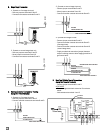
HEAT
(UP)
OFF
(MID)
VENT
(DOWN)
Start-Up Instructions
13