


18
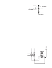
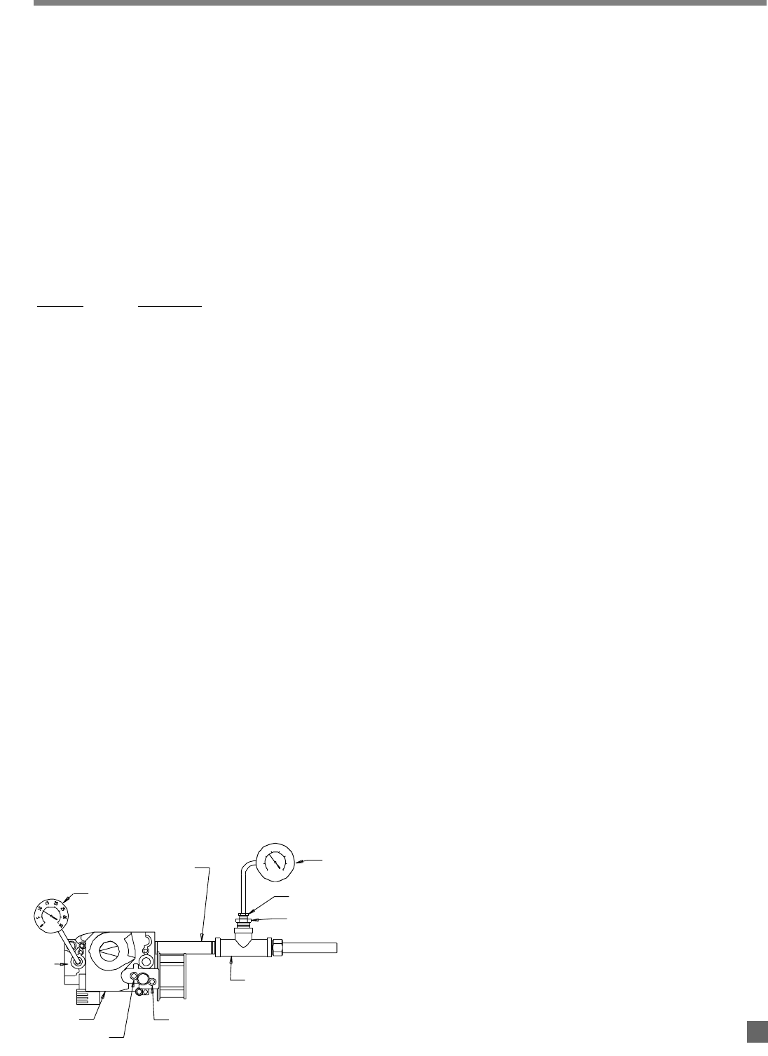
GAUGE 00764
NIPPLE, 1/2 IN
LO
HI
TEE, 1/2 IN
BUSHING, 1/4 IN X 1/8 IN
BUSHING, 1/2 IN X 1/4 IN
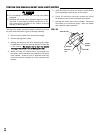
GAS CONTROL
GAUGE 00764
OFF
ON
OUTLET
PRESSURE
TAP
0
5
10
20
25
30
35
15
ATTENTION
■
The following explains a typical procedure to be followed
in checking gas pressures.
■ Consult the dataplate on the heater or page 4 in this
manual for specific pressures to be used in conjunction
with this procedure. The gas pressures will vary
depending upon fuel type.
■ Gas pressure measured at the inlet to the gas valve is
Inlet Pressure and gas pressure measured at the outlet
of the gas valve is Burner Manifold Pressure.
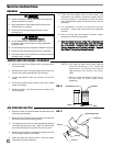
MATERIALS REQUIRED
(To be secured through local purchase)
QQuuaannttiittyy DDeessccrriippttiioonn
2 Gas pressure gauges capable of reading
up to 35 in. W.C. (may also be ordered
from L.B. White, part number 00764)
1 1/2 in. Tee
1 Bushing, 1/2 in. x 1/4
1 Bushing, 1/4 in. x 1/8
A. PPreparation
1. Disconnect the heater from the electrical supply and
close the fuel supply valve to the heater inlet.
2. Remove gas hose and sediment trap from heater.
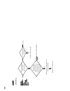
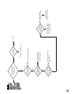
3. Assemble the hardware components together as
shown in Fig. 14.
4. Open the case access panel at gas inlet end of
heater.
5. Brush or blow off any dust or dirt in the vicinity of the
gas control valve.
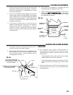
B. GGauge IInstallation
1. Locate the outlet pressure tap, see Fig. 14. Remove
the pressure tap plug using a 3/16 in. allen key.
2. Securely connect a pressure gauge at this pressure
tap, and at the tee adapter at heater inlet. See Fig.
14.
3. Open the fuel supply valves to the heater, reconnect
the heater electrical supply, and start the heater.
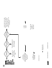
C. RReading PPressures
1. With the heater operating, the pressure gauges
should read the pressures specified on the dataplate.
2. Do the readings at the inlet and outlet pressure
gauges agree with that specified on the dataplate?
If so, then no further checking or adjustment is
required. Proceed to section D.
3. If the inlet pressures do not agree with that specified
on the dataplate, then the regulator controlling gas
pressure to the heater requires adjustment.
4. If the inlet pressure is correct but the burner manifold
pressure does not agree with that specified on the
dataplate, then the HI and LO heat output feature of
the gas control valve requires adjustment.
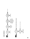
5. Turn the thermostat down to its lowest setting.
Remove the cap from the HI and LO heat adjusting
screws at the two stage pressure regulator on the gas
control valve.
6. Slowly turn up the thermostat until the valve opens in
first stage position and a pressure is read of no
greater than 1.3 in. W.C. (L.P.) or .8 in. W.C. (N.G.) at
the outlet pressure gauge. If less than 1.3 in. W.C.
(L.P.) or .8 in. W.C. (N.G.) is read, the LO heat setting
at the regulator on the gas control will require
adjusting. Turn clockwise to increase, or
counterclockwise to decrease.
7. Turn the thermostat completely up. You should see
the valve open at second stage position and the gas
pressure increase from 1.3 in. W.C. (L.P.) or .8 in. W.C.
(N.G.) at first stage heat to 5.2 in. W.C. (L.P.) or 3.1 in.
W.C. (N.G.) second stage heat. If less or greater than
5.2 in. W.C. (L.P.) or 3.1 in. W.C. (N.G.), the HI heat
setting must be adjusted clockwise or
counterclockwise accordingly until proper pressure is
achieved.
D. CCompletion
1. Once the proper inlet and burner manifold pressures
have been confirmed and/or properly set, close the
fuel supply valve to the heater and allow the heater to
burn off any gas remaining in the gas supply line.
2. Disconnect the heater from its electrical supply.
3. Remove the gauges, gas hose, and tee.
4. Install pressure tap plug.
5. Reconnect sediment trap and gas hoses.
6. Open fuel supply valve. Start the heater and check
for gas leaks.
7. Set thermostat to desired temperature.
Gas Pressure Checks
FIG. 14