


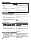
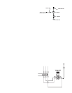
HEAT
POWER CORD
SELECTOR SWITCH
VENT
WHITE
WHITE
WHITE
WHITE
WHITE
WHITE
BLACK
BLACK
BLACK
BLACK
BLACK
BLACK
BLACK
GREEN
JUMPER
TERMINAL
STRIP
CONTROL POWER VENT
CONTROL POWER HEAT
GROUND
7
6
5
4
3
2
1
NEUTRAL(S) FROM
CONTROL POWER
VENT MODE
CONTACTS
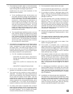
HEAT
POWER CORD
SELECTOR SWITCH
VENT
WHITE
WHITE
WHITE
WHITE
WHITE
WHITE
WHITE
WHITE
WHITE
BLACK
BLACK
WHITE
BLACK
BLACK
BLACK
BLACK
BLACK
BLACK
BLACK
GREEN
JUMPER
TERMINAL
STRIP
FROM CONTROLLER
TO CONTROLLER
GROUND
7
6
5
4
3
2
1
BLACK
12
VENT
MODE
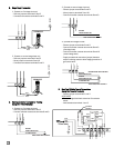
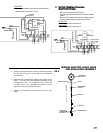
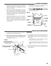
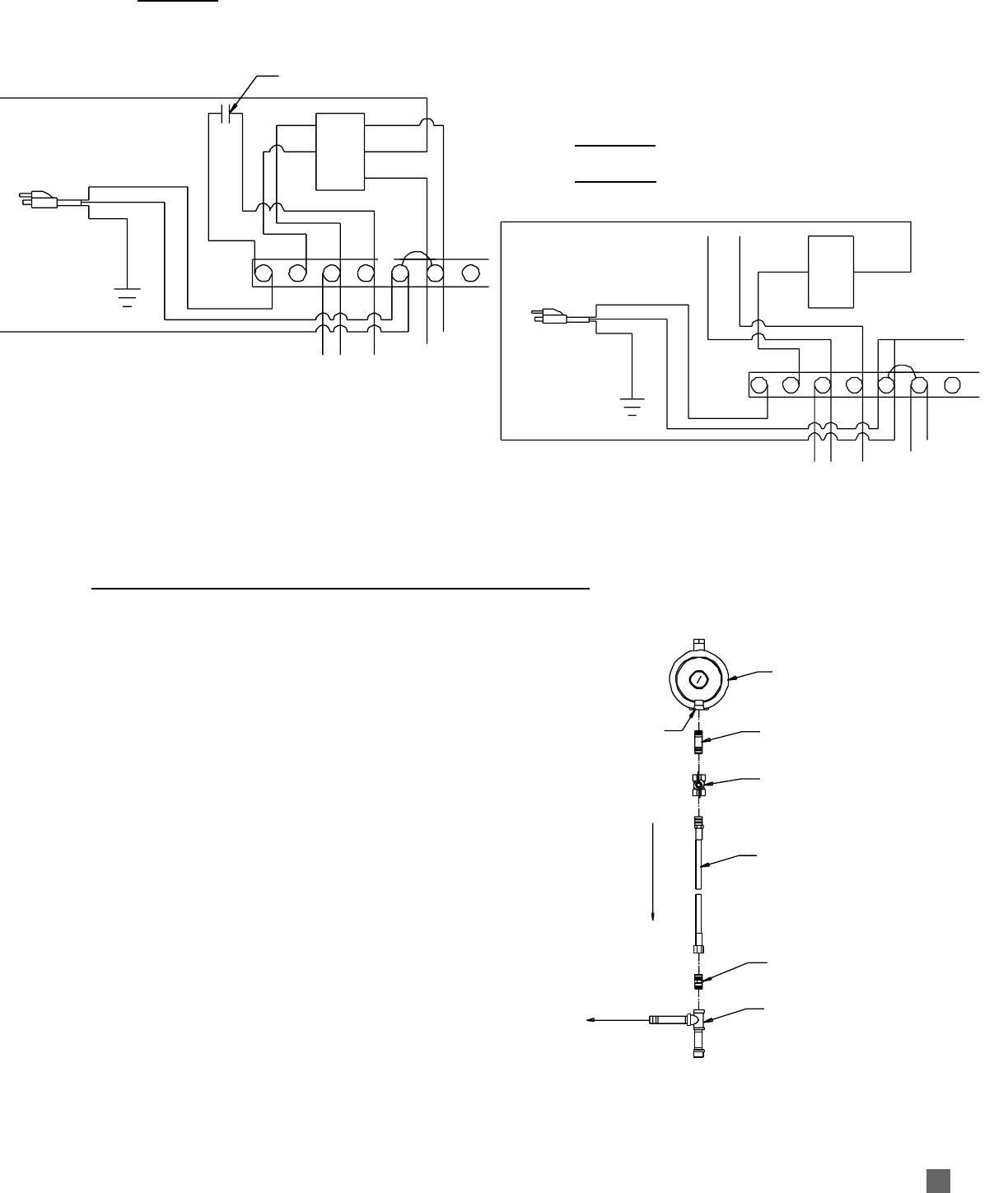
-- Remove black lead at terminal 4 to selector switch.
-- Add contacts at terminals 1 and 4.
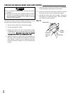
E. Heat-VVent BBuilding CControl CConnections
(Using PPowered CContacts)
-- Remove jumper at terminals 1 and 2.
-- Remove black leads at terminals 3 and 4 to selector
switch.
-- Remove white leads at terminal 6 to selector switch.
-- Add neutral(s) of control contacts at terminal 5.
HEAT MODE
-- Add control power at terminal 3.
VENT MODE
-- Add control power at terminal 4.
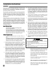
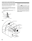
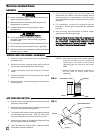
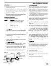
MANUAL SHUT-OFF VALVE, HOSE
AND REGULATOR ASSEMBLY
REGULATOR
NIPPLE
VALVE, MANUAL
SHUT-OFF
GAS HOSE
ADAPTER
SEDIMENT TRAP
TO CONTROL
VALVE INLET
REGULATOR VENT
GAS FLOW
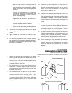
1. Always use approved pipe thread compound suitable
for use with L.P. gas or natural gas on the threaded
connections.
2. Assemble the components together according to the
figure. This view is to show general assembly of the
components only. The regulator must always be
mounted so its vent, regardless of location on the
regulator, is always pointed downward.
3. Tighten all connections securely and check for gas
leaks.
FIG. 5
SECOND STAGE
REGULATOR