


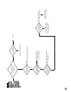
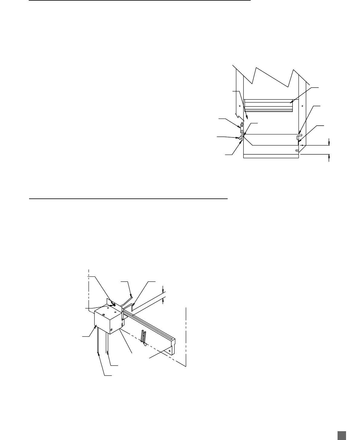
SENSOR
IGNITER
3/16 IN.
HEAT CHAMBER FACE
BURNER
IGNITER LEAD
SENSOR LEAD
ENCLOSURE
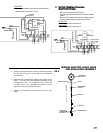
TO REMOVE IGNITER / SENSOR ASSEMBLY
REMOVE SCREW, LIFT ASSEMBLY
FROM ITS MOUNTING SLOTS
TO GAP IGNITER, LOOSEN SCREW.
MOVE ENCLOSURE UP OR DOWN
TO ALLOW PROPER POSITIONING
OF IGNITER TO BURNER.
16
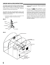
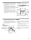
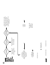
1. The igniter and sensor assembly is located within a
metal enclosure on the heater chamber.
2. Remove the screw that secures the assembly to the
heat chamber and disconnect the respective leads
from the ignition control. Lift the assembly from its
mounting slots. See Fig. 11.
FIG. 11
IMPORTANT
■ The assembly may require cleaning due to
accumulations of dust and dirt over a period of time,
thereby affecting its ability to ignite fuel gas and sense
burner flame.
-- If spark appears to be weak, briskly rub the igniter
electrode with emery cloth or steel wool.
--- If the spark appears strong but the heater cycles off,
briskly rub the sensor rod with emery cloth or steel
wool.
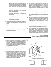
■ Ensure the igniter gap is 3/16 in. and the igniter tip is
positioned over the burner slot according to the
illustration below.
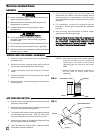
IGNITER AND FLAME SENSOR
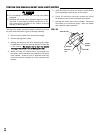
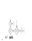
BLOWER OUTLET
OF HEATER
AIR PROVING
SWITCH
ARM OF
FLAPPER
AIR PROVING
SWITCH ARM
FAN WHEEL
PIVOT POINT
OF FLAPPER
EDGE OF
FLAPPER
PIVOT POINT
OF FLAPPER
FLAPPER
31.7 MM TO 34.9 MM
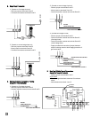
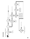
1. Ensure there is not any dust, dirt, etc. that may cause
binding on the pivot points of the flapper. If debris is
found, use a soft brush, or compressed air, to clean
the area as necessary.
2. The arm of the flapper should engage the arm of the
airflow switch when the trailing edge of the flapper
body is lifted and is at the proper clearance distance
off the blower housing bottom. At this distance you
will hear a click which are the contacts closing within
the switch mechanism.
3. If the switch contacts do not close within this
distance, manually push in the arm in the switch to
make sure the switch is not defective. If a click is
heard, the switch is generally considered good.
However, to ensure switch contacts do close, perform
a continuity test
4. If the switch is not defective, the flapper arm may
need adjustment to engage the switch arm.
5. Using a needle nose pliers, gently bend up the arm of
the flapper
(NOT TTHE SSWITCH AARM)
in increments
until the flapper arm engages the switch arm, closing
the contacts of the switch.
FIG. 10
clearance
1 - 1 1/4 In.
FLAPPER ADJUSTMENT