


11
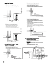
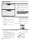
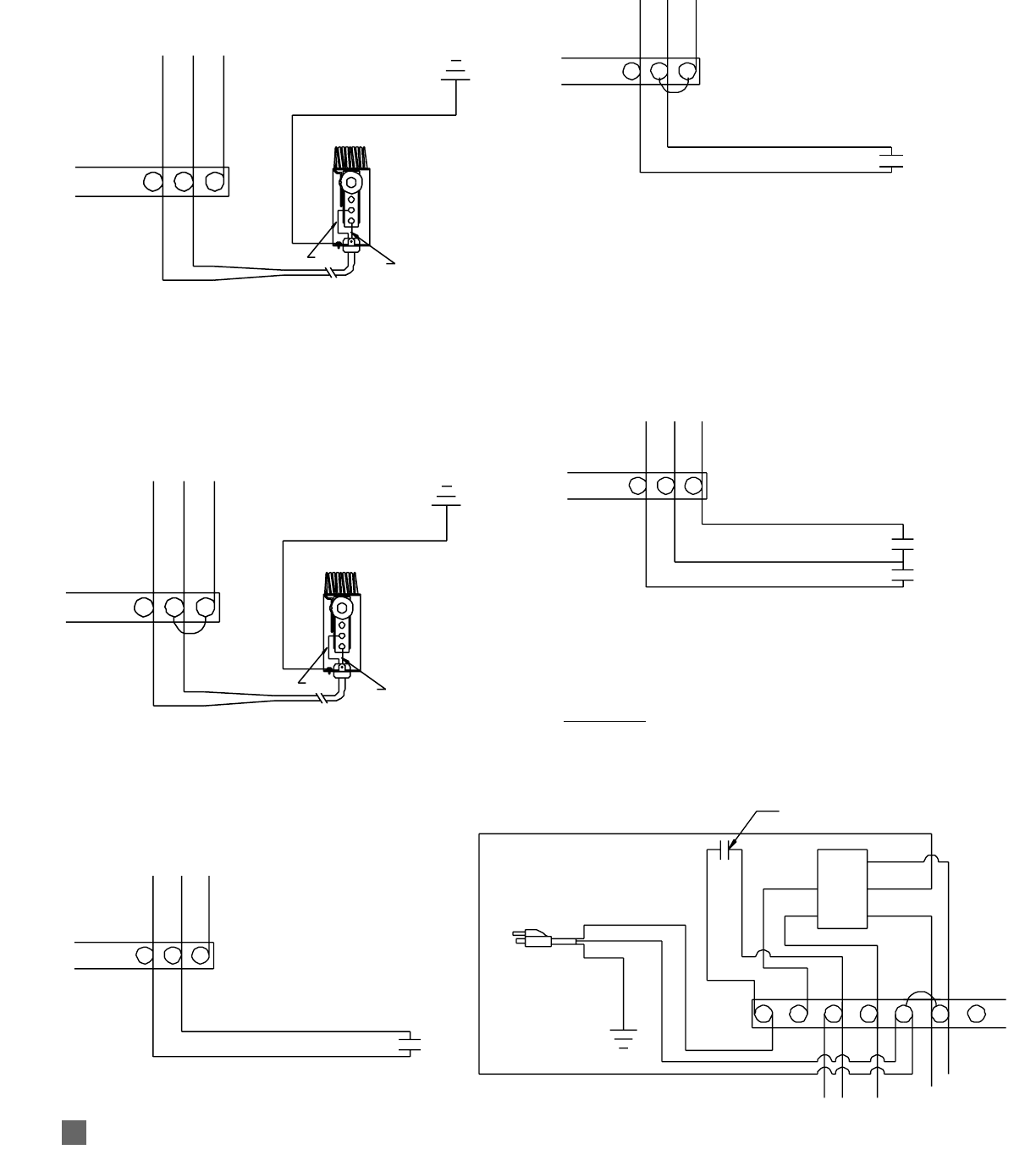
B. Single SStage TThermostat
1. Operate on first stage heat only.
-- Remove jumper at terminals 8 and 9.
-- Connect thermostat to terminals 8 and 9.
2. Operate on second stage heat only.
-- Remove jumper at terminals 8 and 9.
-- Move jumper to terminals 9 and 10.
-- Connect thermostat to terminals 8 and 9.
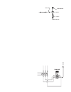
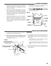
C. Building CController CConnections - HHeating
(Using NNon-PPower CContacts)
1. Operate on first stage heat only.
-- Remove jumper at terminals 8 and 9.
-- Connect controller contacts in terminals 8 and 9.
2. Operate on second stage heat only.
-- Remove jumper at terminals 8 and 9.
-- Move jumper to terminals 9 and 10.
-- Connect controller contacts at terminals 8 and 9.
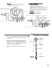
3. Operate both stages of heat.
-- Remove jumper at terminals 8 and 9.
-- Connect controller contacts at terminals 8 and 9
(first stage heat).
-- Connect controller contacts at terminals 9 and 10
(second stage heat).
-- Supply an electrical connection (jumper) between
relays in building control to allow staging transition of
gas control valve.
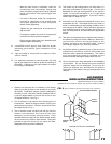
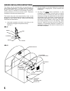
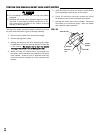
D. Heat-VVent BBuilding CControl CConnections
(Using NNon-PPowered CContacts)
-- Remove jumper at terminals 1 and 2.
HEA
T MODE
-- Remove single black lead at terminal 3 to selector
switch.
-- Add contacts at terminals 1 and 3.
RETURN
FROM CONTROLLER
BROWN
YELLOW
YELLOW
8
9
10
SECOND STAGE HEAT CONTACT
TO CONTROLLER
FIRST STAGE HEAT CONTACT
RETURN
FROM CONTROLLER
RETURN
FROM CONTROLLER
BROWN
YELLOW
YELLOW
8
9
10
FIRST STAGE HEAT CONTACT
TO CONTROLLER
HEAT MODE
CONTACTS
HEAT
POWER CORD
SELECTOR SWITCH
VENT
WHITE
WHITE
WHITE
WHITE
WHITE
WHITE
WHITE
WHITE
WHITE
BLACK
BLACK
WHITE
BLACK
BLACK
BLACK
BLACK
BLACK
BLACK
BLACK
GREEN
JUMPER
TERMINAL
STRIP
FROM CONTROLLER
TO CONTROLLER
GROUND
7
6
5
4
3
2
1
BLACK
THERMOSTAT
GROUND
BROWN
YELLOW
YELLOW
WHITE
BLACK
8
9
10
WHITE
BLACK
JUMPER
THERMOSTAT
GROUND
BROWN
YELLOW
YELLOW
WHITE
BLACK
8
9
10
WHITE
BLACK
RETURN
FROM CONTROLLER
BROWN
YELLOW
YELLOW
8
9
10
FIRST STAGE HEAT CONTACT
TO CONTROLLER
JUMPER