


6
17. Install the valve cores. 18. Install the R-410A thermal expansion valve specified for this
system in the indoor coil.
NOTE: R-410A systems use only thermal expansion valves.
19. Pressurize the lines and indoor coil with a pressure not to
exceed 20 psig.
20. Leak test the lines with a pressure not to exceed 20 psig.
21. Open the suction and liquid service valves fully.
22. Insulate the suction line with refrigerant line insulation
material of ¹⁄₄" or more wall thickness.
23. Pack insulating material around refrigerant lines where they
penetrate the structure to protect the lines and to minimize
vibration transmission.
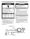
Connect Refrigerant Lines
Refrigerant lines must be connected by a licensed, EPA certified
refrigerant technician in accordance with established procedures.
IMPORTANT:
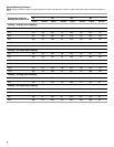
■ Connecting refrigerant lines must be clean, dehydrated,
refrigerant-grade copper lines. Heat pumps should be
installed only with specified line sizes for approved system
combinations with elevation differences up to 15 ft and total
length of up to 50 ft. See the Suction Line Sizes and Liquid
Line Sizes charts later in this section.
■ Avoid sharp bends or possible kinking in the refrigerant lines
during installation as this may cause a reduction in
performance.
■ Use care with the refrigerant lines during the installation
process. Sharp bends or possible kinking in the lines will
cause a reduction in performance.
■ To avoid contamination of the refrigerant system, do not
remove the caps from the lines or system connection points
until connections are ready to be completed.
Install Thermal Expansion Valve
W4GH6 heat pumps are designed for use with thermal expansion
valve systems only. An R-410A system will not operate properly
with an R-22 thermal expansion valve.
Thermal expansion valves equipped with Chatleff-type fittings are
available from the manufacturer. See Thermal Expansion Valve
Kits chart in “System Requirements.”
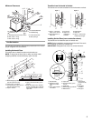
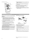
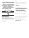
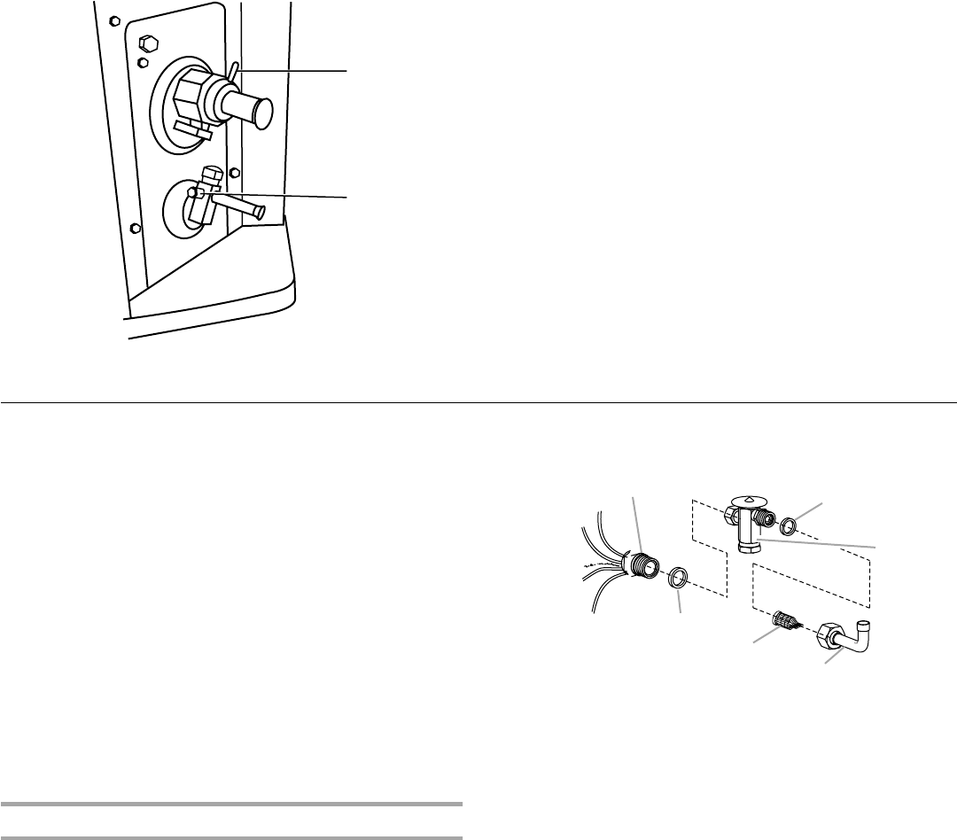
Thermal Expansion Valve Installation
To install the thermal expansion valve:
1. Separate the distributor assembly.
2. If a piston orifice is installed, remove the piston orifice and old
Teflon
®
seal and discard.
3. Insert nozzle end of the thermal expansion valve along with a
new Teflon
®
seal into the distributor.
4. Tighten to 20 to 30 ft lbs. Use backup wrench on all wrench
flats.
NOTE: Overtightening may crush the Teflon
®
seal and cause
a leak.
5. Attach liquid line portion of distributor assembly along with
new Teflon
®
seal to the inlet of the thermal expansion valve.
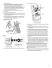
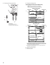
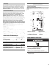
A. Suction pressure tap
B.Liquid pressure tap
A
B
A.Distributor
B. Teflon
®
seal
C. Thermal expansion valve
D.Liquid line stub
E. Strainer
F. Te flo n
®
seal
A
B
C
D
E
F
®Teflon is a registered trademark of E.I. Dupont de Nemours and
Company.