


13
Time Delay
The time delay is 5 minutes long. The delay helps to protect the
compressor from short cycling in case the power to the heat
pump is interrupted or a pressure switch opens. The delay is
bypassed by placing the timer select jumper across the TEST
pins for 0.5 seconds.
Pressure Switch Circuit
The defrost control includes LO-PS terminals to connect an
optional low pressure (loss of charge pressure) switch. A high
pressure switch (optional) can be connected to the HI PS
terminals. See “Defrost Control Board” in the “Adjust Defrost
System” section.
During a single demand cycle, the defrost control will lock out
the heat pump after the fifth time that the circuit is interrupted by
any pressure switch wired to the control board. In addition,
the diagnostic LEDs will indicate a locked-out pressure switch
after the fifth occurrence of an open pressure switch. See
Defrost Control Board Diagnostic LEDs chart later in this section.
The heat pump will remain locked out until power to the board is
interrupted, then re-established, or until the jumper is applied to
the TEST pins for 0.5 seconds.
NOTE: The defrost control board ignores input from the low
pressure switch terminals during:
■ TEST mode
■ Defrost cycle
■ 90-second start-up period
■ First 90 seconds after the reversing valve switches heat/cool
modes
NOTE: If the TEST pins are jumpered and the 5-minute delay is
being bypassed, the LO PS terminal signal is not ignored during
the 90-second start-up period.
Adjust Defrost System
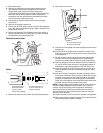
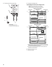
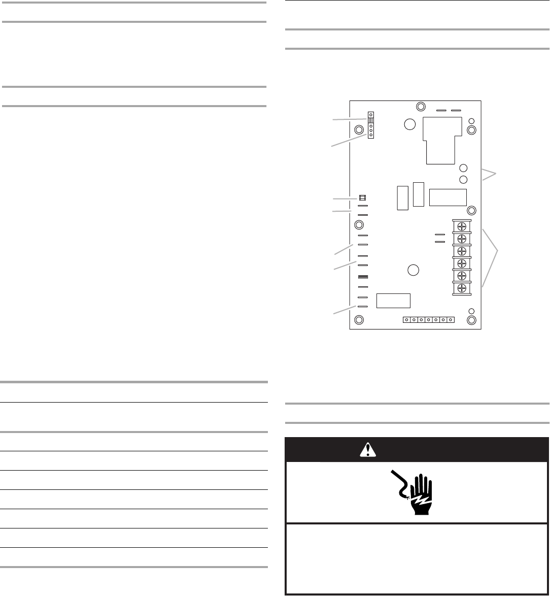
Defrost Control Board
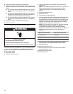
Optional high pressure switch connections
NOTE: To add the pressure switch, remove the factory-installed
jumper.
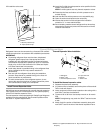
Adjust Time Between Defrost Cycles
1. Disconnect power.
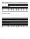
Defrost Control Board Diagnostic LEDs
Mode
Green
LED (DS2)
Red LED
(DS1)
No Power to Board Off Off
Normal Operation/Power to Board Simultaneous Slow Flash
Short Cycle Lockout Alternating Slow Flash
Low Pressure Switch Fault Off Slow Flash
Low Pressure Switch Lockout Off On
High Pressure Switch Fault Slow Flash Off
High Pressure Switch Lockout On Off
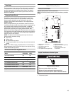
A. Defrost time setting pins
B. Test pins
C.Compressor delay pins
D. Reversing valve
E. Low pressure switch (optional)
F. Defrost thermostat
G. High pressure switch (optional)
H. Diagnostic LEDs
I. Low voltage terminal strip
connections
K1 Relay
K2 Relay
FAN
DS1
L
24V
P2
P5
O-OUT
DF
Y1-OUT
HI-PS
U1
U2
DS2
K3 Relay
P6
TST PS DF C R O Y1
C5
LO-PS
C2
P1
30
60
90
TEST
W1
C
L
R
Y1
O
H
I
A
B
C
D
E
F
G
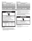
WARNING
Electrical Shock Hazard
Disconnect power before servicing.
Replace all parts and panels before operating.
Failure to do so can result in death or electrical shock.