15
TROUBLESHOOTING
Heat Pump Fails to Operate Properly
Review “Sequence of Operation” and visually inspect the heat
pump before troubleshooting:
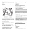
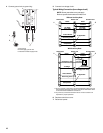
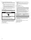
System Diagnostic Module
W4GH6 heat pumps contain a diagnostic module for
troubleshooting heat pump system failures. By monitoring and
analyzing data from the compressor and thermostat demand, the
module can accurately detect the cause of electrical and system
related failure without any sensors. If a system problem occurs, a
flashing LED indicator communicates the failure code.
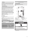
LED Description
Power LED (Green) indicates voltage is present at the power
connection of the module.
Alert LED (Yellow) communicates an abnormal system condition
through a unique flash code. The Alert LED will flash a number of
times consecutively, pause, and then repeat the process. The
number of consecutive flashes correlates to a particular
abnormal condition.
Trip LED (Red) indicates there is a demand signal from the
thermostat but no current to the compressor is detected by the
module. The Trip LED typically indicates the compressor
protector is open or may indicate missing supply power to the
compressor.
Diagnostic LEDs Interpretation
When an abnormal system condition occurs, the diagnostic
module displays the appropriate Alert and/or Trip LED. The
yellow Alert LED will flash a number of times consecutively,
pause, and then repeat the process. To identify a flash code
number, count the number of consecutive flashes. Refer to the
Flash Codes chart for information on the flash codes.
Every time the module powers up, the last Alert LED flash code
that occurred prior to shutdown is displayed for 60 seconds. The
module will continue to display the previous flash code until the
condition returns to normal or 24 VAC is removed from the
module. Trip and Alert LED’s flashing at the same time means
control circuit voltage is too low for operation.
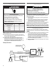
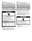
WARNING
Electrical Shock Hazard
Disconnect power before servicing.
Replace all parts and panels before operating.
Failure to do so can result in death or electrical shock.
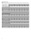
Flash Codes
LED Status Fault Description Troubleshooting Information
Power (Green) Module has power. ■ Supply voltage is present at module terminals.
Trip (Red) Thermostat demand signal Y1
is present, but the
compressor is not running.
■ Compressor protector is open.
■ Outdoor unit power disconnect is open.
■ Compressor circuit breaker or fuse(s) is open.
■ Broken wire or connector is not making contact.
■ Low pressure switch is open, if present in system.
■ Compressor contactor has failed to open.
Alert (Yellow) Flash Code 1 Long Run Time: Compressor
is running extremely long run
cycles.
NOTE: Not applicable on heat
pump models.
Alert (Yellow) Flash Code 2 System Pressure Trip:
Discharge or suction pressure
out of limits or compressor is
overloaded.
■ High head pressure.
■ Condenser coil has poor air circulation (dirty, blocked,
damaged).
■ Condenser fan is not running.
■ Return air duct has substantial leakage.
■ If low pressure switch is present in the system, go to Flash Code
1 information.