


2
Tools and Parts
Gather the required tools and parts before starting installation.
Read and follow the instructions provided with any tools listed
here.
Tools Needed
Parts Needed
Check local codes and HVAC supplier. Check existing electrical
supply, and read “Electrical Requirements,” “Location
Requirements,” “System Requirements” and “Connect
Refrigerant Lines.”
System Requirements
Heat pump system matches are derived from actual laboratory
testing of matched systems. It is recommended that only
matching equipment be used to ensure proper operation and
efficient performance.
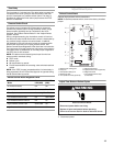
■ The designed system matches are listed in the heat pump
unit specification sheets and on the heat pump refrigerant
charging instructions located on the back of the service
access panel.
■ Refrigerant charging instructions include a list of matching
indoor equipment with the proper thermal expansion valve
size and amount of refrigerant charge required.
■ This heat pump has been factory charged with a quantity of
refrigerant (R-410A) sufficient for a matched indoor coil and a
maximum 15 ft of refrigerant line.
■ In order to maintain the 16 SEER rating, this heat pump must
be matched with an indoor section containing a variable
speed blower.
■ Refer to the refrigerant charge label located on the inside of
the heat pump access panel for the correct thermal
expansion valve size required.
■ This product has been designed and manufactured to meet
ENERGY STAR
®
criteria for energy efficiency when matched
with appropriate coil components. However, proper
refrigerant charge and proper airflow are critical to achieve
rated capacity and efficiency. Installation of this product
should follow the manufacturer’s refrigerant charging and
airflow instructions. Failure to confirm proper charge and
airflow may reduce energy efficiency and shorten equipment
life.
■ A filter drier approved for use with R-410A refrigerant is
installed in the heat pump.
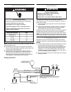
■ If this condensing unit is equipped with a crankcase heater, it
should be energized 24 hours before the condensing unit is
started to prevent compressor damage as a result of
slugging.
■ Use only polyol ester oils if oil must be added to the system.
Mineral oil is not compatible with refrigerant.
Indoor System Thermal Expansion Valve
■ W4GH6 units are designed for use with thermal expansion
valve systems only. The thermal expansion valve must be
ordered separately from the manufacturer.
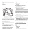
Location Requirements
■ This heat pump is designed to be located outdoors with
sufficient clearance for free entrance to the inlet and
discharge air openings. The location must also allow for
adequate service access. See “Minimum Clearances.”
■ Where possible, select a location for the heat pump which is
shaded from the direct rays of the sun most of the time. North
or east locations are usually most desirable. Position the heat
pump to avoid direct contact with water, snow or ice from a
roofline overhead.
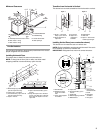
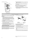
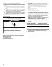
■ The heat pump must be installed on a solid, level mounting
pad that will not settle or shift. Isolate the pad from the
building structure to avoid possible transmission of sound or
vibration from the heat pump into the conditioned space.
■ The heat pump foundation should be raised to a minimum of
3" above finish grade. In areas which have prolonged periods
of temperatures below freezing, and/or snowfall, the heat
pump should be elevated above the average snow line. If
heat pump is to be installed on a flat roof, it should be on a
platform or other support which will raise the inlet air opening
12" minimum above the surface of the flat roof.
■ Care should be taken to ensure free drainage of condensate
from defrost cycles. This will prevent ice accumulation. The
heat pump should be located away from walkways to prevent
possible icing from defrost condensate.
■ Avoid placing the heat pump near areas such as sleeping
quarters or study rooms. Normal operating sound levels may
be objectionable if the heat pump is placed near certain
rooms. A shift in sound type does occur during the defrost
mode. The defrost mode generally lasts no longer than
10 minutes.
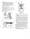
■ Torc h
■ ¹⁄₄" nut driver
■ ⁵⁄₁₆" nut driver
■ Adjustable wrench
■ Gauge set for R-410A
refrigerant
■ Service wrench with hex-
head extension
■ Torque wrench
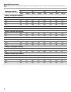
Thermal Expansion Valve Kits
Model Part Number
W4GH624 H4TXV01
W4GH636 H4TXV02
W4GH648, 60 H4TXV03