


3
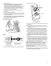
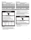
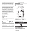
Minimum Clearances
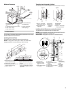
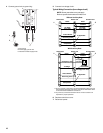
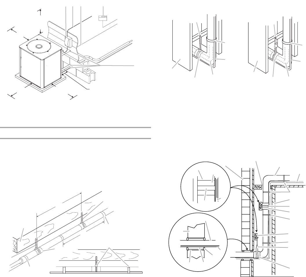
Line Set Isolation
The following illustrations demonstrate procedures which ensure
proper refrigerant line set isolation.
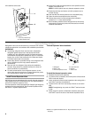
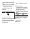
Installing Horizontal Runs
This shows how to install line sets on horizontal runs.
NOTE: To hang line set from joist or rafter, use either metal
strapping material or anchored heavy nylon wire ties.
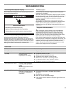
Transition from Horizontal to Vertical
This shows how to make a transition from horizontal to vertical.
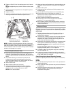
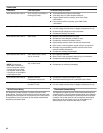
Installing Vertical Runs (new construction shown)
This shows how to install line sets on vertical runs.
NOTE: Similar installation practices should be used if line set is
to be installed on exterior of outside wall.
IMPORTANT: Refrigerant lines must not contact structure.
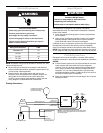
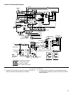
A. Weatherproof disconnect switch
B. NEC class 1 wiring
C. NEC class 2 wiring
D. House thermostat
E. Seal openings
A. Metal strapping material
(around vapor line only)
B. Floor joist or roof rafter
C. Anchored heavy nylon wire tie
(around vapor line only)
D. Tape or wire tie
E.Metal sleeve
F. Tape or anchored heavy nylon
wire tie
G. Strap the vapor line to the floor
joist or roof rafter at 8" intervals,
then strap the liquid line to the
vapor line.
48" Overhead
Clearance
(Discharge
Air)
To
Power
Supply
To
Indoor
Unit
To
Indoor
Coil
30" Service
Access Clearance
36" Clearance
(Inlet Air)
12" Clearance Between
Unit and Building
12" Clearance
(Inlet Air)
AB C D
E
B
C
D
E
F
A
G
8'
8'
A. Style 1—anchored
heavy nylon wire tie
B. Strap liquid line to
vapor line.
C. Liquid line
D. Vapor line—
wrapped in
armaflex
E. Metal sleeve
F. Wall stud
G. Style 2—automotive
muffler-type hanger
A. Outside wall
B. Refrigerant lines
must not contact
wall.
C. Vapor line wrapped
in armaflex
D. Liquid line
E. Anchored heavy nylon
wire tie
F. Inside wall
G. Metal strapping material
H. Metal sleeve
I. Wood block
between studs
J. Caulk
K.Fiberglass
insulation
L. PVC pipe
A
F
E
D
C
B
G
F
E
D
C
B
Style 1
Style 2
A
B
C
D
E
F
G
H
E
I
E
G
H
C
A
D
J
K
L
C
D
G
H